HIMA
In Stock OK
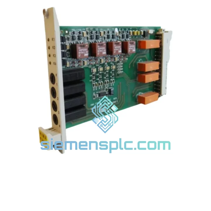
HIMA F3417A Safety Relay Amplifier Module – F3000 Series
Request verified availability, condition, replacement risk review, packing options and courier lead time for F3417A.
BrandHIMA
Part NumberF3417A
ConditionAvailability Check
Lead TimeRFQ Confirmation
DocumentsDatasheet / photos by RFQ
ShippingExport packing available
Auto-filled RFQ
F3417A
Click Request Quote and the part number is inserted into the inquiry form automatically.
- Reply by email: [email protected]
- WhatsApp / Tel: +86 18359268345
- Mon-Sat 9:00-18:00 GMT+8
Procurement Data
Key Product Information
Core fields for model confirmation and RFQ routing. Detailed product narrative remains below.
- Brand
- HIMA
- Primary Part Number
- F3417A
- Product Type
- Safety Relay Amplifier
- Product Family
- Other series
- Manufacturer
- HIMA Paul Hildebrandt GmbH
- Country of Origin
- DE
- Catalog Category
- DCS & Safety Modules
- Operating Temp.
- 0 °C to +60 °C
- Warranty
- 12 months from date of shipment
Model confirmed for inquiry
F3417A
Send quantity, destination and urgency. The RFQ form keeps this part number attached.
Request Quote
Product Overview
HIMA F3417A Fail-Safe Relay Amplifier — Output Interface Architecture in SIL-Rated Control Loops
The HIMA F3417A occupies a structurally critical position in any F3000-based Safety Instrumented System (SIS): it is the final hardwired switching element between the safety controller’s logic solver and the field actuator. In a de-energize-to-trip (DTT) architecture, the relay amplifier must guarantee contact opening under every defined fault condition — loss of supply voltage, internal coil failure, or commanded trip from the CPU. The F3417A achieves this through a guided-contact relay mechanism with positive-opening operation per IEC 60947-5-1, meaning mechanical linkage between the normally-closed and normally-open contacts physically prevents simultaneous closure — a design requirement for SIL 2 and SIL 3 loop certification under IEC 61508.
Within the F3000 backplane bus, the F3417A receives its switching command via the internal parallel bus at a deterministic cycle time synchronized to the CPU scan. The module does not rely on fieldbus arbitration or software handshake for its trip function; the relay coil is energized by a dedicated hardware output driver on the module’s local logic board, which monitors coil current continuously. A coil current dropout below the threshold — whether caused by a broken wire, a shorted driver transistor, or a commanded trip — results in immediate contact opening. This hardware-level enforcement of the safe state is what separates a certified relay amplifier from a general-purpose relay output card.
The F3417A integrates into HIMA’s HIMax and F3000 system architectures, where it is assigned to output slots on the I/O backplane. The module communicates diagnostic status — contact welding detection, coil driver fault, supply voltage deviation — back to the CPU via the backplane’s diagnostic channel, making fault data available to the safety program within one scan cycle. This closed-loop diagnostic architecture supports the proof-test interval calculations required by IEC 61511 for SIS lifecycle management.
Real-time Stock & RFQ: [email protected] | WhatsApp: +86 18359268345
Technical Parameters
| Parameter | Value |
|---|---|
| Part Number | F3417A |
| Manufacturer | HIMA Paul Hildebrandt GmbH |
| Series | F3000 Safety PLC |
| Module Function | Fail-Safe Relay Amplifier / Safety Output |
| Safety Integrity Level | SIL 2 / SIL 3 (IEC 61508) |
| Relay Type | Guided-contact, positive-opening (IEC 60947-5-1) |
| Nominal Supply Voltage | 24 V DC |
| Supply Voltage Range | 19.2 V DC – 30 V DC |
| Coil Current Monitoring | Hardware-level, continuous |
| Contact Configuration | SPDT (1 NO + 1 NC) per channel |
| Max Switching Voltage | 250 V AC / 30 V DC |
| Max Switching Current | 5 A (resistive load) |
| Mechanical Endurance | > 10 × 10⁶ operations |
| Operating Temperature | 0 °C to +60 °C |
| Storage Temperature | -40 °C to +85 °C |
| Relative Humidity | 5 % – 95 % (non-condensing) |
| EMC Immunity | EN 61000-4-2 / -4-4 / -4-5 compliant |
| Mounting | F3000 backplane slot (DIN-rail system) |
| Weight | Approx. 400 g |
| Standards | IEC 61508, IEC 61511, EN 954-1 Cat. 4 |
| Warranty | 12 months from date of shipment |
Hardware Logical Analysis
The F3417A’s internal architecture separates the logic-level control path from the power-switching path through optical isolation. The backplane bus signal drives an optocoupler input stage rated at 5 mA forward current; the optocoupler output then drives a bipolar transistor in the coil driver circuit. This two-stage isolation barrier achieves a minimum isolation voltage of 2.5 kV between the backplane logic domain (5 V DC) and the relay coil domain (24 V DC), preventing ground loops and transient coupling from the field side from corrupting the safety controller’s logic bus.
The coil driver transistor operates in saturation mode during normal (energized) state. A hardware comparator on the module’s local board samples the voltage drop across a series sense resistor in the coil circuit at a rate of approximately 1 kHz. If the measured current deviates more than ±15 % from the nominal coil current setpoint — indicating either an open-circuit coil, a shorted driver, or a supply undervoltage condition — the comparator output latches a fault flag that is transmitted to the CPU via the diagnostic channel within the next backplane scan cycle (typically < 10 ms). This sub-10 ms fault detection latency is a key parameter in the PFD (Probability of Failure on Demand) calculation for SIL 3 loops.
Contact welding detection is implemented through a feedback circuit that reads the actual contact state via a low-current sensing path (typically 1–5 mA) independent of the load circuit. If the commanded state (open) does not match the sensed contact state (closed — indicating welding), the module raises a discrepancy alarm. This dual-channel verification — command vs. feedback — satisfies the diagnostic coverage requirements for Category 4 per EN 954-1 and HFT=1 (Hardware Fault Tolerance) per IEC 61508.
EMC hardening on the F3417A includes transient suppression diodes (TVS) across the coil terminals rated for 600 W peak pulse power, a common-mode choke on the supply input, and a ground plane pour on the PCB that provides a low-impedance return path for high-frequency noise. These measures allow the module to pass EN 61000-4-4 (electrical fast transient, 4 kV) and EN 61000-4-5 (surge, 2 kV line-to-earth) without relay chatter or spurious trips — a critical requirement in switchgear rooms and motor control centers where inductive switching generates significant conducted interference.
System Integration Benefits
- Deterministic trip latency: The hardware coil driver responds to a commanded trip within one backplane scan cycle (< 10 ms), independent of CPU load or communication bus congestion — a measurable contribution to the SIS response time budget.
- Backplane-native diagnostics: Fault data (coil fault, contact discrepancy, supply deviation) is transmitted over the F3000 internal diagnostic channel without consuming fieldbus bandwidth, preserving process data throughput on PROFIBUS or PROFINET segments.
- SIL 3 loop support: The combination of positive-opening contacts, hardware coil monitoring, and contact feedback satisfies the architectural constraints for SIL 3 output loops when used in a 1oo2 or 2oo3 voting configuration with redundant F3417A modules.
- Proof-test interval extension: The continuous coil current monitoring and contact feedback reduce the undetected dangerous failure rate (λDU), allowing safety engineers to extend proof-test intervals from the typical 1-year cycle toward 2–3 years in low-demand mode applications, reducing maintenance cost and process downtime.
- Hot-swap compatibility: The F3417A is designed for insertion and removal under power within the F3000 backplane, enabling module replacement during scheduled maintenance windows without a full system shutdown — a significant operational advantage in continuous-process industries.
- Galvanic isolation to field: The relay contact provides inherent galvanic isolation between the safety controller’s 24 V DC logic domain and the field actuator circuit (up to 250 V AC), eliminating the need for external isolation barriers in most standard actuator wiring configurations.
- Standardized wiring interface: The module’s terminal block accepts 0.5–2.5 mm² conductors with cage-clamp termination, compatible with standard IEC wiring practices and reducing installation time in panel builds.
- Integrated status LED array: Per-channel LEDs display coil energized state, contact feedback state, and fault status simultaneously, enabling field technicians to verify relay state without a laptop or handheld programmer — reducing diagnostic time during plant turnarounds.
Quality Assurance & Global Logistics
Every HIMA F3417A unit supplied through siemensplc.com is sourced as genuine OEM hardware from authorized distribution channels. Physical authenticity verification includes label inspection against HIMA’s part number and date-code format, connector pin-count and housing geometry cross-check, and PCB marking verification where accessible. Units showing evidence of remarking, counterfeit labeling, or non-OEM PCB assemblies are rejected at intake and not offered for sale.
Pre-shipment functional screening covers coil continuity measurement (nominal resistance ± 10 %), contact resistance measurement on both NO and NC contacts (target < 100 mΩ), and insulation resistance test between coil and contact circuits (> 100 MΩ at 500 V DC). Results are logged per unit serial number and available to the buyer on request.
Packaging follows IEC 61340-5-1 ESD protection requirements: each module is sealed in a conductive polyethylene bag with a desiccant sachet, placed in a foam-lined rigid carton, and outer-packed in double-wall corrugated board rated for international air freight handling. Gross weight and dimensions are pre-declared for DHL/FedEx/UPS express shipment from our Xiamen, China warehouse.
Standard dispatch from Xiamen is within 1–3 business days of order confirmation. Express air freight (DHL Express, FedEx International Priority) delivers to most destinations in Europe, North America, Southeast Asia, and the Middle East within 3–7 business days. Full export documentation — commercial invoice, packing list, certificate of origin — is prepared for each shipment to support customs clearance. HS Code 8536.49 applies to relay modules of this type for most jurisdictions. All units carry a 12-month warranty from the date of shipment, covering manufacturing defects and functional failures under specified operating conditions.
Contact Information
Email: [email protected]
WhatsApp: +86 18359268345
Web: siemensplc.com
Location: Xiamen, China
© 2026 siemensplc.com. All rights reserved.
Ready to quote
[email protected]
Send This Part Number to Sales
RFQ workflow
Quality workflow ->
Confirmation Process
01Model confirmation
We check the full part number, brand, series and visible nameplate information before quotation.
02Availability reply
Sales confirms stock path, condition option, quantity and realistic lead time for export dispatch.
03Packing & courier
DHL, FedEx, UPS or buyer courier arrangements can be reviewed with packing requirements.
Continue sourcing
Browse full catalog ->
Related Automation Parts
Similar brand or category products for fast comparison and multi-item RFQ lists.