Honeywell
RFQ Ready
Honeywell TK-ODD321 Discrete Output Module – Safety Manager
Safety Manager
Origin US
Discrete Output Module
Request verified availability, condition, replacement risk review, packing options and courier lead time for FS-IOBUS-HBR.
Click Request Quote and the part number is inserted into the inquiry form automatically.
Core fields for model confirmation and RFQ routing. Detailed product narrative remains below.
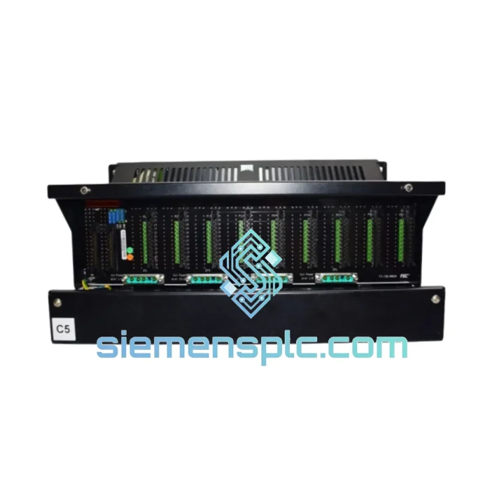
The Honeywell FS-IOBUS-HBR is the dedicated hardware chassis that forms the physical and electrical backbone of redundant I/O subsystems within the Honeywell Safety Manager FS (Fail-Safe) platform. Unlike general-purpose DIN-rail carriers, this chassis is purpose-engineered to host dual-path I/O bus communication — the HBR suffix denoting its Hot-standBy Redundant bus architecture — making it a non-negotiable structural element in any SIL 2 or SIL 3 safety instrumented system (SIS) built on the Safety Manager platform.
In a typical Safety Manager rack assembly, the FS-IOBUS-HBR chassis provides the mechanical mounting slots and the internal backplane traces that carry both the primary and secondary I/O bus signals simultaneously. Each slot on the chassis presents a dual-connector interface to the installed I/O module: one connector routes to Bus A, the other to Bus B. The Safety Manager CPU continuously arbitrates between both paths at the hardware level, with switchover latency measured in microseconds — well within the process safety time (PST) margins required by IEC 61511 for most process industry applications.
The chassis is rated for operation in Class I, Division 2 / Zone 2 hazardous area environments when installed within a suitably certified enclosure, and its backplane is designed to maintain signal integrity under conducted and radiated EMI conditions consistent with IEC 61000-4 series test levels. Internal bus termination resistors are factory-fitted, eliminating field-wiring errors that could compromise bus impedance matching and introduce reflections on the differential signal pairs.
From a system architecture standpoint, the FS-IOBUS-HBR chassis is the physical instantiation of the Safety Manager’s 1oo2D (one-out-of-two with diagnostics) I/O voting logic. Each I/O module installed in the chassis reports its field-side measurements independently over Bus A and Bus B. The Safety Manager CPU compares both readings on every scan cycle — typically 10 ms to 100 ms depending on configuration — and flags any discrepancy exceeding the configured diagnostic threshold as a detected dangerous failure, triggering the appropriate safe-state output action without requiring operator intervention. This architecture achieves a diagnostic coverage (DC) figure exceeding 99% for the I/O subsystem, a prerequisite for SIL 3 hardware fault tolerance calculations under IEC 61508-2.
The chassis backplane also carries the 24 V DC module power rail, distributed from the system power supply unit (PSU) through a dedicated power bus separate from the signal bus. This physical separation prevents power supply noise from coupling into the differential I/O bus lines — a design discipline that directly reduces the probability of common-cause failures (CCF) between the power and communication subsystems. The power rail includes per-slot electronic fusing, so a short-circuit on one module’s power input does not propagate to adjacent slots or collapse the bus voltage for the entire chassis.
Mechanically, the FS-IOBUS-HBR chassis is constructed from a zinc-coated steel frame with an anodized aluminum backplane substrate. The surface finish provides a low-impedance ground reference plane that bonds all installed module chassis grounds to a single equipotential, suppressing ground loop currents that would otherwise appear as common-mode noise on analog input channels. Module retention is achieved through a dual-latch mechanism — a front-panel lever latch and a rear captive screw — ensuring modules remain seated under the vibration profiles specified in IEC 60068-2-6 (sinusoidal, 10–150 Hz, 1 g).
For maintenance operations, the FS-IOBUS-HBR supports online module replacement without de-energizing the chassis. When a module is extracted, the Safety Manager CPU detects the slot vacancy within one scan cycle and transitions that I/O channel group to its configured safe state. Upon reinsertion of a replacement module, the CPU performs an automatic module identity check — verifying part number, firmware revision, and configuration checksum — before restoring the channel group to operational status. This sequence is logged in the Safety Manager audit trail with timestamps, supporting the traceability requirements of functional safety management systems per IEC 61511-1 Clause 5.
Real-time Stock & RFQ: [email protected] | WhatsApp: +86 18359268345
| Part Number / SKU | FS-IOBUS-HBR |
| Manufacturer | Honeywell Process Solutions |
| Product Series | Safety Manager FS (Fail-Safe) Series |
| Function | Redundant I/O Bus Chassis (Hot-standBy Redundant) |
| Bus Architecture | Dual-path differential serial bus (Bus A / Bus B), simultaneous active |
| Bus Switchover Latency | Microsecond-range, transparent to CPU scan cycle |
| Module Slot Count | Per chassis configuration (consult system documentation for slot count variant) |
| Module Power Rail | 24 V DC, per-slot electronic fusing, isolated from signal bus |
| Backplane Substrate | Anodized aluminum with zinc-coated steel frame |
| Ground Architecture | Single equipotential ground plane, all slots bonded |
| Bus Termination | Factory-fitted internal termination resistors |
| Operating Temperature | 0 °C to +60 °C (consult Honeywell datasheet for extended range options) |
| Storage Temperature | –40 °C to +85 °C |
| Relative Humidity | 5% to 95% non-condensing |
| Vibration Resistance | IEC 60068-2-6: 10–150 Hz, 1 g sinusoidal |
| EMC Compliance | IEC 61000-4 series (conducted and radiated immunity) |
| Hazardous Area Rating | Class I, Division 2 / Zone 2 (within certified enclosure) |
| Safety Integrity Level | SIL 2 / SIL 3 capable (system-level, per IEC 61508-2) |
| Diagnostic Coverage (DC) | >99% for I/O subsystem |
| Hot-swap Support | Yes — online module replacement without chassis de-energization |
| Weight | 270 g |
| Country of Origin | USA |
| Condition | Genuine new / surplus new (specify at inquiry) |
| Warranty | 12 months from date of shipment |
The FS-IOBUS-HBR’s most consequential design decision is the physical separation of the two bus signal paths at the backplane trace level. Bus A and Bus B are routed on independent copper layers of the backplane PCB, with a ground plane layer interposed between them. This stackup geometry provides approximately 40 dB of inter-bus isolation at frequencies up to 10 MHz, ensuring that a fault on one bus — whether a short to supply, an open-circuit trace, or a transient induced by a nearby contactor switching event — cannot capacitively or inductively couple into the redundant bus path. The result is that the two buses satisfy the independence requirement for redundant channels specified in IEC 61508-2 Table A.14.
The per-slot electronic fusing on the 24 V DC power rail uses solid-state current-limiting devices rather than traditional resettable polyfuses. Solid-state limiters respond to overcurrent conditions within microseconds, compared to the tens-of-milliseconds response time of polyfuses. This speed advantage prevents the transient voltage droop that a slow-acting fuse would allow to propagate across the shared power bus, protecting adjacent modules from a brown-out condition that could cause spurious output state changes — a particularly critical concern for safety digital output (SDO) modules driving final elements.
The dual-latch module retention mechanism addresses a failure mode that is frequently underestimated in vibration-prone installations: partial module ejection. A module that is 80% seated may maintain electrical continuity on most pins while losing contact on the high-frequency bus signal pins, which typically have shorter contact wipe lengths. The FS-IOBUS-HBR’s rear captive screw provides a secondary retention force independent of the front lever latch, ensuring full pin engagement is maintained even under sustained vibration at the IEC 60068-2-6 test profile. This eliminates the intermittent bus fault signature that partial ejection produces — a fault mode that is difficult to diagnose remotely and can generate nuisance safe-state trips.
The single equipotential ground plane architecture directly addresses the common-mode rejection ratio (CMRR) of analog input modules installed in the chassis. When multiple analog input modules share a chassis with digital output modules, the switching currents of the digital outputs can induce ground potential differences between module chassis grounds if those grounds are not bonded to a common reference. The FS-IOBUS-HBR’s low-impedance ground plane — achieved through the zinc-coated steel frame and multiple ground bonding points per slot — keeps inter-module ground potential differences below 10 mV under worst-case switching conditions, preserving the ±0.1% full-scale accuracy of the analog input channels.
Every Honeywell FS-IOBUS-HBR unit supplied by siemensplc.com is sourced through verified industrial channels — authorized distributor surplus, OEM-direct excess inventory, or documented plant decommissions with full traceability records. No grey-market, counterfeit, or refurbished-as-new units are accepted into our inventory. Each unit undergoes a three-stage incoming inspection: visual examination of label integrity, connector pin condition, and housing markings; electrical continuity check of backplane bus traces and power rail pins; and firmware/revision verification where applicable.
Units are stored in an ESD-controlled warehouse environment in Xiamen, China, maintained at 20–25 °C and 40–60% RH, consistent with Honeywell’s recommended storage conditions for electronic assemblies. Outbound packaging uses anti-static foam-lined cartons with desiccant packs, meeting ISTA 2A transit testing requirements for air and ground freight.
Logistics from Xiamen reach major industrial hubs on the following typical transit schedules: Southeast Asia 2–4 business days (DHL Express); Middle East 3–5 business days (FedEx International Priority); Europe 4–6 business days; North America 5–7 business days. Sea freight consolidation is available for multi-unit orders where lead time permits. All shipments include commercial invoice, packing list, and certificate of conformance. Export compliance screening is performed on every order against applicable control lists.
A 12-month warranty from date of shipment covers all units against manufacturing defects and DOA (Dead on Arrival) conditions. Warranty claims are processed within 5 business days of receipt of the returned unit at our Xiamen facility.
Email: [email protected]
WhatsApp: +86 18359268345
Web: siemensplc.com
Location: Xiamen, China
© 2026 siemensplc.com. All rights reserved.
We check the full part number, brand, series and visible nameplate information before quotation.
Sales confirms stock path, condition option, quantity and realistic lead time for export dispatch.
DHL, FedEx, UPS or buyer courier arrangements can be reviewed with packing requirements.
Similar brand or category products for fast comparison and multi-item RFQ lists.