Honeywell
RFQ Ready
Honeywell CC-PDOB11 Digital Output Module – Experion PKS C300
Experion PKS
Origin US
Digital Output Module
Request verified availability, condition, replacement risk review, packing options and courier lead time for MC-TDOR12.
Click Request Quote and the part number is inserted into the inquiry form automatically.
Core fields for model confirmation and RFQ routing. Detailed product narrative remains below.
The MC-TDOR12 (assembly revision 51309148-175) occupies a well-defined position in Honeywell’s I/O hierarchy: it is the discrete relay output interface between the DCS controller and field-side actuators that demand galvanically isolated, voltage-agnostic switching contacts. Unlike solid-state output modules that impose a fixed output voltage rail, the MC-TDOR12 presents twelve independent SPDT dry contacts to the field, making it compatible with 24 VDC solenoid coils, 120 VAC motor starter coils, and 48 VDC annunciator circuits within the same termination assembly — without any external signal conditioning. This architectural flexibility is the primary reason the module remains a standard spare in refineries, power stations, and chemical plants that have operated TDC 3000 infrastructure for two or more decades.
From a control-loop perspective, the MC-TDOR12 sits at the final execution layer. The Honeywell C200 or C300 controller resolves its logic scan, writes a Boolean state to the output tag, and the LCN or FTE backplane propagates that state to the module within one scan cycle. The relay coil energizes in under 10 ms, and the contact closure is confirmed back to the controller via the module’s built-in output readback path — providing closed-loop verification of actuator command without additional field wiring. This deterministic command-to-confirmation latency is critical in emergency shutdown sequences where IEC 61511 SIL-rated response times must be documented and auditable.
📦 Real-time Stock & RFQ: [email protected] | WhatsApp: +86 18359268345
| Parameter | Specification |
|---|---|
| Manufacturer | Honeywell Process Solutions |
| Part Number | MC-TDOR12 |
| Assembly Revision | 51309148-175 |
| Module Function | 12-Channel Digital Relay Output Board |
| Output Contact Type | SPDT dry-contact relay (Form C) |
| Output Channels | 12 independent relay points |
| Contact Rating — DC | 2 A @ 30 VDC (resistive); 0.5 A @ 30 VDC (inductive, L/R ≤ 7 ms) |
| Contact Rating — AC | 0.5 A @ 125 VAC (resistive) |
| Minimum Switchable Load | 10 mA @ 5 VDC |
| Mechanical Relay Life | > 10,000,000 operations (no load); > 100,000 operations (rated load) |
| Electrical Isolation | Optical isolation, field-to-logic; 1,500 VAC dielectric withstand |
| Command-to-Contact Latency | < 10 ms (coil energize); < 5 ms (coil de-energize) |
| Output Readback | Hardware contact-state readback to controller (closed-loop verification) |
| Platform Compatibility | Honeywell TDC 3000 (AM, HPM, APM); Experion PKS (HC, C200, C300, C300E) |
| Communication Interface | Local Control Network (LCN) / Fault-Tolerant Ethernet (FTE) |
| Backplane Power | 5 VDC logic rail (supplied via ITA backplane) |
| Operating Temperature | 0 °C to +60 °C |
| Storage Temperature | -40 °C to +85 °C |
| Relative Humidity | 5 % to 95 % RH, non-condensing |
| EMC Compliance | IEC 61000-4-2 (ESD), IEC 61000-4-4 (EFT), IEC 61000-4-5 (Surge) |
| Safety Certifications | CE, UL Listed (process control equipment) |
| Form Factor | Single-slot DCS I/O card, ITA-mounted |
| Module Weight | 820 g |
| Country of Origin | United States of America |
| Warranty | 12 months from date of shipment (manufacturing defects) |
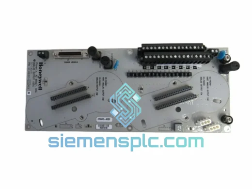
The MC-TDOR12’s internal architecture separates into three functional planes: the backplane communication interface, the relay drive logic, and the field termination layer.
Backplane Communication Interface: The module implements a parallel I/O register mapped to the LCN node address assigned during ITA configuration. On each controller scan, the HPM or C300 writes a 12-bit output word to this register. The register latches the state and drives the relay coil drivers independently of subsequent scan cycles — meaning a relay remains energized even if the backplane communication is momentarily interrupted, preventing spurious de-energization during network transients. This latch-on-last-state behavior is a deliberate safety design: in most process applications, an unexpected valve closure or motor stop is more hazardous than a brief communication gap.
Relay Drive Logic and EMC Design: Each relay coil is driven by a dedicated transistor stage with a flyback suppression diode across the coil terminals. This clamps the inductive kickback voltage to approximately 1 V above the supply rail, protecting the drive transistor and eliminating the high-frequency transient that would otherwise couple into adjacent signal wiring through parasitic capacitance. The optical isolator between the logic-side transistor and the field-side contact circuit provides a common-mode rejection ratio (CMRR) exceeding 60 dB at 50/60 Hz, which is sufficient to suppress ground-loop noise in marshalling cabinets where field cables from multiple voltage domains share the same tray.
Contact Readback Path: A secondary optical isolator samples the actual contact state (not the coil drive state) and feeds it back to the logic register. This distinction is architecturally significant: the controller can detect a welded contact (coil de-energized but contact still closed) or a broken contact (coil energized but contact open), enabling the DCS alarm system to flag a field device fault without requiring a separate discrete input module for contact verification. In SIL-rated loops, this readback eliminates one layer of external diagnostic wiring.
Thermal Management: The relay array is arranged in two rows of six, with the coil dissipation distributed across the PCB surface area. At full load (all 12 relays energized simultaneously), the total coil dissipation is approximately 1.8 W — well within the convective cooling capacity of the standard ITA enclosure at 60 °C ambient. No forced-air cooling is required, which is consistent with the TDC 3000 cabinet design philosophy of passive thermal management for long-term reliability in unmanned substations.
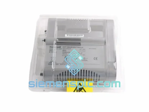
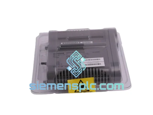
Every MC-TDOR12 51309148-175 unit dispatched from our Xiamen, China facility undergoes a structured pre-shipment verification protocol. Visual inspection confirms PCB marking integrity, component date codes, and Honeywell label authentication against known-good reference units — a necessary step given the prevalence of counterfeit DCS I/O modules in the secondary market. Functional bench testing applies backplane-equivalent power and simulates LCN register writes to verify all 12 relay channels switch correctly and that the contact readback path returns accurate state data. Units that pass are photographed, assigned a serialized inspection record, and packaged in anti-static bags within foam-lined export cartons rated for air freight handling.
Logistics from Xiamen to global destinations is executed via DHL Express, FedEx International Priority, and UPS Worldwide Expedited, with typical transit times of 3–5 business days to Europe, North America, and Southeast Asia. For bulk orders, sea freight consolidation via Xiamen Port is available with full export documentation: commercial invoice, packing list, certificate of origin, and HS code declaration (HS 8537.10) for customs clearance. All shipments include real-time tracking and are covered by cargo insurance. A 12-month warranty against manufacturing defects is provided from the date of shipment, with replacement or credit issued upon confirmed failure analysis.
Email: [email protected]
WhatsApp: +86 18359268345
Web: siemensplc.com
Location: Xiamen, China
© 2026 siemensplc.com. All rights reserved.
We check the full part number, brand, series and visible nameplate information before quotation.
Sales confirms stock path, condition option, quantity and realistic lead time for export dispatch.
DHL, FedEx, UPS or buyer courier arrangements can be reviewed with packing requirements.
Similar brand or category products for fast comparison and multi-item RFQ lists.