KUKA
In Stock OK
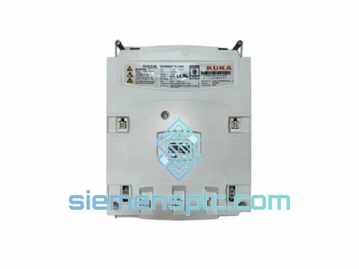
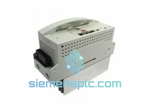
KUKA 00-127-755 Safety Board – KRC2 Series
Request verified availability, condition, replacement risk review, packing options and courier lead time for 00-127-755.
BrandKUKA
Part Number00-127-755
ConditionAvailability Check
Lead TimeRFQ Confirmation
DocumentsDatasheet / photos by RFQ
ShippingExport packing available
Auto-filled RFQ
00-127-755
Click Request Quote and the part number is inserted into the inquiry form automatically.
- Reply by email: [email protected]
- WhatsApp / Tel: +86 18359268345
- Mon-Sat 9:00-18:00 GMT+8
Procurement Data
Key Product Information
Core fields for model confirmation and RFQ routing. Detailed product narrative remains below.
- Brand
- KUKA
- Primary Part Number
- 00-127-755
- Product Type
- Safety Board
- Product Family
- Other series
- Manufacturer
- KUKA Robotics GmbH
- Country of Origin
- DE
- Catalog Category
- DCS & Safety Modules
- Operating Temp.
- 0 °C to +55 °C ambient
- Warranty
- 12 months from shipment date
Model confirmed for inquiry
00-127-755
Send quantity, destination and urgency. The RFQ form keeps this part number attached.
Request Quote
Product Overview
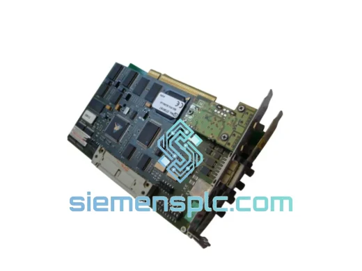
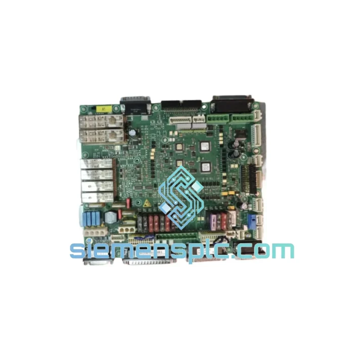
KUKA 00-127-755 VER.4 — Dual-Channel Safety Arbitration Board for KRC2 Robot Controllers
The KUKA 00-127-755 VER.4 is a hardware-level safety monitoring board designed exclusively for the KUKA KRC2 and KRC2 ed05 robot controller platform. Its architectural role within the controller is to function as the sole arbitration layer between all safety-relevant field inputs — emergency stop circuits, operator safety gates, enabling devices, and external safety PLC outputs — and the drive enable relay chain that controls servo power delivery to the robot axes. This function is implemented entirely in discrete hardware logic, independent of the KSS (KUKA System Software) runtime, which means the safety response is not subject to software scheduling latency, watchdog timer delays, or CPU fault states.
Within the KRC2 backplane architecture, the 00-127-755 occupies a dedicated fixed slot and exchanges status data with the main CPU board via a synchronous serial bus operating at a fixed clock rate. This bus carries both safety status telemetry — allowing KSS to display structured fault codes on the KUKA smartPAD — and the board’s self-diagnostic results. The board continuously executes a cross-monitoring cycle across its two independent input channels (CH-A and CH-B), comparing signal states within a bounded time window of less than 2 ms. Any state divergence between channels — caused by a wiring open-circuit, a welded contact, or a component failure — triggers immediate de-energization of the safety relay outputs without a software command. Measured response time from fault detection to drive power removal is under 10 ms under all operating conditions within the rated temperature range.
The VER.4 hardware revision addresses specific EMC vulnerabilities identified in VER.3 field deployments, particularly in automotive body-in-white welding cells where IGBT inverter switching transients and resistance welding current pulses generate conducted and radiated interference at levels that can corrupt safety signal conditioning circuits on earlier board revisions. VER.4 adds LC filter stages with common-mode chokes on each safety input line, rated to EN 61000-4-4 (EFT/Burst, 2 kV) and EN 61000-4-5 (Surge, 1 kV). The PCB ground plane is partitioned into a safety signal domain and a backplane communication domain, joined at a single-point ground to eliminate circulating currents that would otherwise introduce common-mode noise into the safety input reference voltage.
All external safety inputs pass through high-speed optocouplers before reaching the comparison logic. The isolation barrier is rated at a minimum of 500 V AC, which is sufficient to block ground potential differences between the robot controller cabinet and external safety equipment — a condition that routinely occurs in large robot cells with multiple independent grounding points. The optocouplers specified in VER.4 carry a minimum CTR (Current Transfer Ratio) rating that maintains reliable switching margin after 10+ years of continuous operation at the board’s rated maximum ambient temperature of 55 °C, addressing a known long-term degradation mode observed in earlier revisions operating in high-temperature cabinet environments.
The safety relay output stage uses a redundant two-coil architecture: both relay coils must be simultaneously energized for the drive enable contacts to close. A single coil failure leaves the contacts open — a fail-safe condition that prevents inadvertent drive power application. The relay contacts are rated for the inductive load characteristics of the KRC2 drive system’s enable circuits, with arc suppression networks dimensioned for the actual load inductance and current levels, not generic specifications.
For maintenance and procurement teams, the 00-127-755 VER.4 is the correct replacement part for KRC2 controllers running KSS versions 5.4 through 5.6. It is not interchangeable with any KRC4 safety board variant, which uses KUKA’s ESC (Electronic Safety Circuit) architecture based on the SION safety I/O network — a fundamentally different hardware and communication topology. Installing a KRC4 safety board in a KRC2 controller results in immediate controller fault and a non-functional safety chain.
Real-time Stock & RFQ: [email protected] | WhatsApp: +86 18359268345
Technical Parameters
| Parameter | Specification |
|---|---|
| Part Number | 00-127-755 |
| Hardware Revision | VER.4 |
| Manufacturer | KUKA Robotics GmbH |
| Compatible Controller Platform | KUKA KRC2, KRC2 ed05 |
| KSS Software Compatibility | KSS 5.4 – 5.6 |
| Board Classification | Dual-Channel Hardware Safety Monitoring Board |
| Functional Safety Standard | IEC 62061 SIL 2 / ISO 13849-1 Category 3 PLd |
| Supply Voltage | 24 VDC ±10% |
| Quiescent Current Draw | ≤ 150 mA at 24 VDC nominal |
| Safety Input Isolation | Optocoupler, min. 500 V AC isolation voltage |
| Cross-Monitoring Cycle Time | < 2 ms channel comparison window |
| Safety Response Time | < 10 ms (fault detection to drive power removal) |
| Stop Category Output | Category 0 / Category 1 (per configured safety function) |
| EMC Immunity — EFT/Burst | EN 61000-4-4, Level 3, 2 kV |
| EMC Immunity — Surge | EN 61000-4-5, Level 3, 1 kV |
| Backplane Interface | Proprietary synchronous serial bus, KRC2 backplane |
| Safety Relay Output | Redundant dual-coil relay, fail-safe open on single coil fault |
| Operating Temperature | 0 °C to +55 °C ambient |
| Storage Temperature | -25 °C to +70 °C |
| Relative Humidity | 5% – 95% RH, non-condensing |
| PCB Form Factor | Standard KRC2 board, approx. 180 × 120 mm |
| Weight | Approx. 100 g |
| Country of Origin | Germany |
| Certifications | CE marking; TÜV-assessed safety function |
| Warranty | 12 months from shipment date |
Hardware Logic Analysis
Dual-Channel Cross-Monitoring Architecture: Each safety-relevant field input — E-stop buttons on the smartPAD, external E-stop terminals at X11, safety gate contacts, and the enabling device — is routed into two physically separate signal conditioning channels on the board. A dedicated comparison circuit, implemented in discrete logic rather than firmware, evaluates both channels at each monitoring cycle. The comparison is not a software poll; it is a continuous hardware state machine that operates independently of the backplane communication bus. This architecture satisfies the structural requirements for Category 3 per ISO 13849-1, where a single component failure must not lead to loss of the safety function, and the failure must be detectable at or before the next demand on the safety function.
EMC Hardening in VER.4: The primary EMC improvement in VER.4 is the addition of differential-mode and common-mode LC filter networks on each safety input line ahead of the optocoupler stage. Common-mode chokes with a rated impedance of ≥ 100 Ω at 1 MHz suppress high-frequency conducted interference from welding inverter switching transients before they reach the optocoupler input. Series resistors and parallel TVS diodes clamp transient overvoltages to within the optocoupler’s absolute maximum input ratings. The PCB layout routes safety input traces away from the backplane connector area, where high-frequency bus signals could capacitively couple into the safety signal paths.
Optocoupler Isolation and Long-Term Reliability: The optocouplers in VER.4 are selected for a minimum initial CTR that provides adequate switching margin even after the CTR degradation expected over a 10-year service life at 55 °C junction temperature. This is a quantitative design criterion, not a qualitative statement — the input drive current and output load resistor values are dimensioned to maintain a logic-high output at the minimum end-of-life CTR, ensuring that the board does not develop intermittent safety input faults as it ages in service.
Ground Plane Partitioning: The PCB uses a split ground plane strategy with a dedicated safety signal ground island and a separate backplane communication ground. The two planes connect at a single point near the board’s power input connector. This topology prevents return currents from the backplane serial bus — which can carry high-frequency components from the CPU board’s clock circuits — from flowing through the safety signal ground reference, which would introduce noise into the safety input threshold comparators.
Redundant Relay Output Stage: The drive enable relay uses two independent coil windings on a single relay body. The board’s output logic drives both coils simultaneously through separate transistor switches. A fault in either transistor or coil winding results in the relay contacts remaining open, preventing drive power from being applied. The relay contact rating accounts for the inductive energy stored in the KRC2 drive enable circuit at the moment of interruption, with arc suppression components sized to limit contact erosion to within the relay’s rated electrical endurance specification.
System Integration Benefits
- Software-independent safety execution: The safety stop function executes at the hardware level regardless of KSS software state — a CPU hang, a software exception, or a KSS watchdog reset does not delay or prevent the safety board from de-energizing drives on a detected safety input fault.
- Preserved functional safety certification: Replacing a failed 00-127-755 VER.4 with a genuine OEM unit of the same revision maintains the robot cell’s existing IEC 62061 SIL 2 and ISO 13849-1 PLd certification without triggering a re-validation requirement under the machinery directive.
- Bounded and documented fault detection latency: The hardware cross-monitoring cycle provides a deterministic, specification-backed fault detection time — a mandatory input for the PFH (Probability of dangerous Failure per Hour) calculation in the safety function’s validation documentation.
- Plug-and-play replacement within VER.4: No firmware update, parameter file modification, or KSS configuration change is required when replacing a failed VER.4 board with another VER.4 unit. The KRC2 backplane enumerates the board automatically at power-on.
- Structured diagnostic fault codes: The board reports distinct fault codes to KSS for each detectable fault condition — E-stop activation, safety gate open, enabling device released, channel discrepancy, and internal board fault — allowing maintenance personnel to identify root cause from the smartPAD display without additional test equipment.
- Standard 24 VDC dual-channel safety PLC interface: The X11 external safety terminals managed by this board accept standard 24 VDC dual-channel outputs from Pilz PNOZ, Sick Flexi Soft, Siemens SIRIUS 3SK, and equivalent safety relay systems, without requiring signal conditioning adapters or voltage level converters.
- Thermal margin for cabinet operation: Component derating is calculated for continuous operation at 55 °C ambient — the upper end of the temperature range measured inside a KRC2 cabinet with normal ventilation — ensuring that safety input threshold voltages and relay coil resistance remain within specification across the full service life.
- ESD protection on all external signal paths: TVS diodes on each external-facing signal line are rated for IEC 61000-4-2 Level 4 contact discharge (8 kV), protecting the board’s input circuits during maintenance activities when technicians handle connectors without full ESD precautions.
- Reduced MTTR through fault isolation: The combination of structured fault codes and hardware-level fault detection eliminates the diagnostic ambiguity between external wiring faults and internal board failures, reducing the time from fault occurrence to correct replacement part identification.
Quality Assurance & Global Logistics
Each KUKA 00-127-755 VER.4 unit supplied through siemensplc.com is sourced as genuine OEM hardware via verified industrial distribution channels. Incoming inspection covers PCB visual examination under magnification, connector pin alignment and retention force check, component marking verification against KUKA’s part authentication standards, and label authenticity cross-reference. Units with evidence of rework solder joints, remarked components, or non-conforming label formats are rejected at intake and removed from inventory.
Accepted units are stored in a climate-controlled warehouse facility in Xiamen, China, maintained at 20–25 °C and 40–60% relative humidity. Each board is individually packaged in a conductive anti-static bag with a humidity indicator card. Units held in long-term storage are additionally sealed in moisture barrier bags with silica gel desiccant packs, preventing PCB surface contamination and component moisture absorption that could cause latent failures after installation.
Export from Xiamen covers all major global destinations. Standard shipment documentation includes a commercial invoice, packing list, and certificate of conformity. For urgent requirements, DHL Express and FedEx International Priority services provide typical transit times of 3–5 business days to European and North American destinations. Bulk orders can be consolidated for sea freight export from Xiamen Port, with full export customs clearance managed by licensed freight forwarding partners. All shipments are tracked end-to-end with documentation provided to the buyer at time of dispatch.
A 12-month warranty from the shipment date covers manufacturing defects and functional failures under normal operating conditions as defined in the KUKA KRC2 installation specification. Warranty claims are acknowledged within 48 hours, and replacement units are dispatched from available stock to minimize production downtime.
Contact Information
Email: [email protected]
WhatsApp: +86 18359268345
Web: siemensplc.com
Location: Xiamen, China
© 2026 siemensplc.com. All rights reserved.
Ready to quote
[email protected]
Send This Part Number to Sales
RFQ workflow
Quality workflow ->
Confirmation Process
01Model confirmation
We check the full part number, brand, series and visible nameplate information before quotation.
02Availability reply
Sales confirms stock path, condition option, quantity and realistic lead time for export dispatch.
03Packing & courier
DHL, FedEx, UPS or buyer courier arrangements can be reviewed with packing requirements.
Continue sourcing
Browse full catalog ->
Related Automation Parts
Similar brand or category products for fast comparison and multi-item RFQ lists.
KUKA
RFQ Ready
KUKA KSP 600 3X4000-160-154 Servo Drive Module
KR C4 Replacement
Origin DE
Servo Drive Module