Mitsubishi Electric
In Stock OK
Mitsubishi F1-12MR Programmable Controller – MELSEC F1 Series
Request verified availability, condition, replacement risk review, packing options and courier lead time for F1-12MR.
BrandMitsubishi Electric
Part NumberF1-12MR
ConditionAvailability Check
Lead TimeRFQ Confirmation
DocumentsDatasheet / photos by RFQ
ShippingExport packing available
Auto-filled RFQ
F1-12MR
Click Request Quote and the part number is inserted into the inquiry form automatically.
- Reply by email: [email protected]
- WhatsApp / Tel: +86 18359268345
- Mon-Sat 9:00-18:00 GMT+8
Procurement Data
Key Product Information
Core fields for model confirmation and RFQ routing. Detailed product narrative remains below.
- Brand
- Mitsubishi Electric
- Primary Part Number
- F1-12MR
- Product Type
- Programmable Logic Controller
- Series / Family
- MELSEC
- Manufacturer
- Mitsubishi Electric Corporation
- Country of Origin
- JP
- Catalog Category
- Relays & Protection
- Operating Temp.
- 0 °C to +55 °C
- Warranty
- 12 months against manufacturing defects; DOA replacement within 7 business days
Model confirmed for inquiry
F1-12MR
Send quantity, destination and urgency. The RFQ form keeps this part number attached.
Request Quote
Product Overview
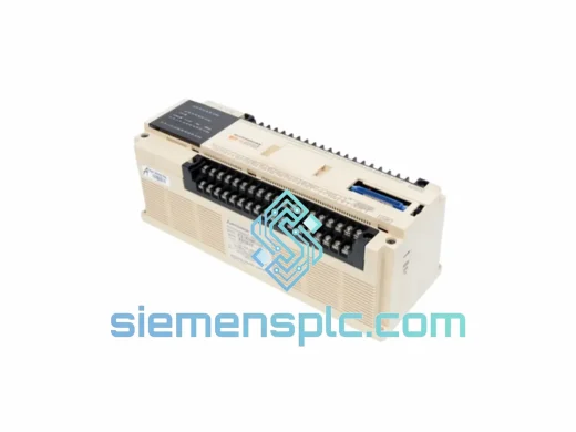
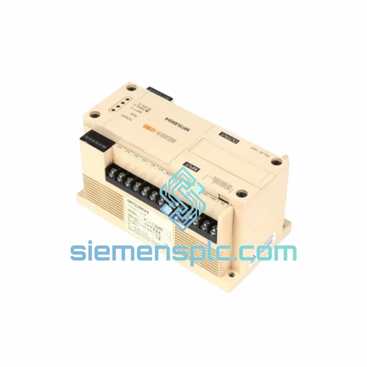
Mitsubishi F1-12MR: Fixed-Configuration Relay Output PLC Base Unit for Discrete Industrial Control
The F1-12MR is a fixed-I/O programmable logic controller base unit from Mitsubishi Electric’s MELSEC F1 sub-series — a platform engineered for deterministic discrete control in standalone machinery, process interlocking, and MRO replacement scenarios. With 6 DC input points and 6 relay output contacts housed in a single compact enclosure, the F1-12MR eliminates the overhead of modular rack architecture for applications where I/O count is defined and stable. Its relay output topology provides galvanic isolation between the PLC logic domain and the field load circuit, making it directly applicable to mixed-voltage environments without external interface relays.
This unit occupies a specific niche in the MELSEC F Series lineage: it predates the FX generation’s expansion bus architecture, operating instead as a self-contained controller with an RS-422 peripheral port for programming and HMI connectivity. For facilities running legacy F1-based machinery, the F1-12MR remains the only drop-in replacement that preserves existing ladder programs, wiring terminations, and panel cutouts without re-engineering.
Real-time Stock & RFQ: [email protected] | WhatsApp: +86 18359268345
Technical Parameters
| Part Number / SKU | F1-12MR |
| Manufacturer | Mitsubishi Electric Corporation |
| Series | MELSEC F1 (F Series) |
| Unit Classification | Base Unit – Fixed I/O Configuration |
| Total I/O Points | 12 (6 Inputs / 6 Relay Outputs) |
| Input Signal | DC 24 V, sink/source compatible, optically isolated |
| Output Type | Relay contact (MR designation), Form A (NO) |
| Output Rated Current | 2 A per point (resistive); 80 VA max per point |
| Output Load Voltage Range | AC 100–240 V / DC 5–30 V |
| Power Supply Input | AC 100–240 V (±10%), 50/60 Hz |
| Program Memory | 1,000 Steps — EEPROM (non-volatile, battery-free) |
| Programming Language | Ladder Diagram (LD) |
| Scan Cycle | ~0.5 ms / 1,000 steps |
| Internal Relay (M) | 256 points |
| Timer (T) | 32 points (100 ms / 10 ms resolution) |
| Counter (C) | 16 points (16-bit up counter) |
| Data Register (D) | 16 points (16-bit) |
| Communication Port | RS-422 (F1 peripheral protocol) |
| Compatible Programmer | F1-20P handheld console; SW0-F1C software |
| Relay Mechanical Life | 10,000,000 operations (no load) |
| Relay Electrical Life | 100,000 operations at rated resistive load |
| Operating Temperature | 0 °C to +55 °C |
| Storage Temperature | −20 °C to +70 °C |
| Relative Humidity | 35–85% RH, non-condensing |
| Vibration Resistance | 10–55 Hz, 0.5 mm amplitude (per IEC 60068-2-6) |
| Dimensions (W × H × D) | ~130 × 90 × 75 mm |
| Weight | ~1,340 g |
| Enclosure Rating | IP20 (panel-mount) |
| Certifications | CE, UL (original production standard) |
| Country of Origin | Japan |
| HS Code | 8537.10 |
| Warranty | 12 months against manufacturing defects; DOA replacement within 7 business days |
Hardware Logical Analysis
The F1-12MR’s internal architecture reflects Mitsubishi Electric’s design philosophy for the early 1980s compact PLC market: maximum reliability through circuit simplicity, with no unnecessary abstraction layers between the CPU and the I/O termination points.
Input Stage — Optical Isolation Architecture: Each of the 6 DC input channels (X0–X5) passes through a dedicated optocoupler. The LED side of the coupler is driven by the 24 VDC field signal through a current-limiting resistor network, while the phototransistor side interfaces directly with the CPU’s input latch register. This arrangement provides a minimum 500 V isolation barrier between field wiring and the CPU logic rail, suppressing common-mode noise transients that are endemic in relay-heavy panel environments. Input filter time constants (typically 10 ms hardware RC filter) further attenuate contact bounce from mechanical field devices, preventing false input registration without software debounce routines.
Output Stage — Relay Contact Topology: The 6 relay output points (Y0–Y5) use electromechanical relay contacts rather than solid-state switching. Each relay coil is driven by a transistor driver stage controlled by the CPU output latch. The contact itself is electrically independent of the PLC logic supply — it can switch AC or DC loads across a wide voltage range (5–240 V) without requiring the load voltage to match the PLC supply. This galvanic isolation is the defining characteristic of the MR (relay) output type: there is no shared reference between the PLC 0 V rail and the load circuit common, eliminating ground loop paths that cause measurement errors in mixed-signal panels.
EMC Design Considerations: The F1-12MR’s power supply section incorporates a line filter on the AC input to attenuate conducted emissions per CISPR 11 Class A requirements. The relay output coil drivers include flyback suppression diodes to clamp the inductive kickback voltage when the relay de-energizes — protecting the output transistor stage from voltage spikes that would otherwise exceed its BVCES rating. The compact PCB layout minimizes loop areas in the high-frequency switching paths, reducing radiated emissions from the internal DC-DC converter.
Program Execution Model: The F1-12MR executes a synchronous scan cycle: (1) Input image refresh — all 6 input states are latched into the input image register at the start of each scan; (2) Program execution — the 1,000-step ladder program is evaluated sequentially against the input image; (3) Output image refresh — the evaluated output coil states are written to the relay driver stage. This deterministic scan model guarantees that all outputs reflect a consistent snapshot of inputs from the same scan cycle, preventing race conditions that can occur in interrupt-driven or asynchronous I/O architectures. At 0.5 ms per 1,000 steps, worst-case input-to-output latency is bounded and predictable — a requirement for safety-adjacent interlocking logic.
EEPROM Program Retention: Unlike earlier PLC generations that used battery-backed CMOS RAM, the F1-12MR stores its ladder program in EEPROM. This eliminates the battery maintenance interval (typically 5–7 years for lithium cells) and the associated risk of program loss on battery depletion. EEPROM write endurance (typically 100,000 cycles) is not a practical constraint for a controller whose program changes infrequently after commissioning.
System Integration Benefits
- Zero-Modification Legacy Replacement: The F1-12MR’s fixed terminal layout and RS-422 port pinout are identical across production runs, enabling direct substitution in existing panels without rewiring or program conversion — critical for minimizing downtime during MRO replacement.
- Mixed-Voltage Load Compatibility: Relay contacts switch AC or DC loads independently of the PLC supply voltage. A single F1-12MR can simultaneously control 24 VDC solenoids and 230 VAC contactors on separate output points without additional interface hardware.
- Deterministic Scan Latency: The synchronous scan architecture bounds worst-case input-to-output response time to one scan cycle (~0.5 ms at full program capacity), enabling reliable implementation of time-critical interlocking sequences without jitter.
- Battery-Free Operation: EEPROM program storage removes the battery replacement interval from the maintenance schedule, reducing lifecycle maintenance cost and eliminating the risk of unplanned program loss in remote or unmanned installations.
- Galvanic I/O Isolation: Optical isolation on inputs and relay contact isolation on outputs provide two independent isolation barriers, preventing fault propagation between field wiring faults and the CPU — a measurable contribution to panel MTBF.
- Universal AC Power Input: The 100–240 VAC wide-range power supply accepts grid voltages across North America, Europe, and Asia without transformer or tap adjustment, simplifying global machine deployment and spare parts standardization.
- RS-422 HMI Connectivity: The F1 peripheral port supports connection to operator panels and SCADA systems using Mitsubishi’s F1 protocol, enabling supervisory visibility into PLC status without adding a separate communication module.
- Compact Panel Footprint: At 130 × 90 × 75 mm, the F1-12MR occupies less panel volume than equivalent modular PLC configurations (CPU rack + I/O modules + power supply), reducing enclosure size and associated material cost in space-constrained installations.
- Proven Long-Term Parts Availability: siemensplc.com maintains verified stock of F1-12MR units sourced through authenticated industrial channels, providing a reliable supply path for facilities that cannot migrate to current-generation PLC platforms without significant re-engineering investment.
Quality Assurance & Global Logistics
Authenticity Verification: Every F1-12MR unit supplied by siemensplc.com undergoes a structured incoming inspection protocol: visual examination of housing, terminal blocks, and connector integrity; label verification against Mitsubishi Electric production markings and date codes; and a functional power-on test confirming CPU initialization, I/O response, and RS-422 port activity. Units that do not pass all inspection criteria are quarantined and not listed for sale.
12-Month Warranty: All units carry a 12-month warranty against manufacturing defects and latent failures. Dead-on-arrival (DOA) units are replaced within 7 business days of confirmed fault report. Warranty claims are processed with a documented RMA procedure — no arbitrary rejection.
Customs Compliance: All shipments are declared under HS Code 8537.10 with accurate commercial invoice values. Export documentation is prepared in compliance with Chinese customs regulations, with ECCN EAR99 classification applicable to most destination countries (no export license required for standard commercial transactions).
Multi-Currency Payment: Orders are accepted via T/T bank transfer, PayPal, Western Union, and major credit cards. Invoices can be issued in USD, EUR, GBP, or CNY depending on buyer preference.
Logistics from Xiamen: Xiamen Gaoqi International Airport and Xiamen Port provide direct access to DHL, FedEx, UPS, and SF International express networks. Standard transit times: 3–5 business days to Europe and North America via express courier; 5–10 business days via economy air freight. All shipments include real-time tracking and are packed in anti-static ESD bags with foam-cushioned outer cartons to protect against transit shock and humidity.
Lead Time: In-stock units ship within 1–2 business days of payment confirmation. For bulk orders or units requiring pre-shipment functional testing documentation, allow 3–5 business days.
Contact Information
Email: [email protected]
WhatsApp: +86 18359268345
Web: siemensplc.com
Location: Xiamen, China
© 2026 siemensplc.com. All rights reserved.
Ready to quote
[email protected]
Send This Part Number to Sales
RFQ workflow
Quality workflow ->
Confirmation Process
01Model confirmation
We check the full part number, brand, series and visible nameplate information before quotation.
02Availability reply
Sales confirms stock path, condition option, quantity and realistic lead time for export dispatch.
03Packing & courier
DHL, FedEx, UPS or buyer courier arrangements can be reviewed with packing requirements.
Continue sourcing
Browse full catalog ->
Related Automation Parts
Similar brand or category products for fast comparison and multi-item RFQ lists.
Mitsubishi Electric
RFQ Ready
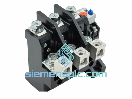
Mitsubishi TH-N12TP Thermal Overload Relay – TH-N Series
TH-N Series
Origin JP
Thermal Overload Relay
Mitsubishi Electric
RFQ Ready
Mitsubishi Electric TH-N12KP Thermal Overload Relay
Motor Protection 7–12A
Origin JP
Thermal Overload Relay
Mitsubishi Electric
RFQ Ready
Mitsubishi S-K25 AC Magnetic Contactor
25A 3-Pole S-K Series
Origin JP
AC Magnetic Contactor