ProvibTech
RFQ Ready
PROVIBTECH TM0182-A50-B00-C00 Proximity Sensor
TM0182 Series
Origin US
Vibration & Proximity Sensor
Request verified availability, condition, replacement risk review, packing options and courier lead time for TM0180-A07-B00-C05-D10.
Click Request Quote and the part number is inserted into the inquiry form automatically.
Core fields for model confirmation and RFQ routing. Detailed product narrative remains below.
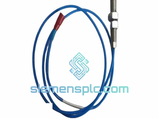
In rotating machinery protection systems, signal chain integrity between the proximity probe and the oscillator/demodulator is not a secondary concern — it is the measurement. The PROVIBTECH TM0180-A07-B00-C05-D10 is a 5-metre armored coaxial extension cable engineered to bridge the physical gap between a TM0180-series eddy-current proximity probe and its paired driver unit without introducing impedance discontinuities, capacitive loading errors, or ground-loop noise that would corrupt shaft displacement readings. This cable is a precision passive component, not a generic coaxial run. Every dimensional and material parameter is defined to maintain the electrical characteristics of the complete probe-cable-driver system as a calibrated measurement loop.
Deployment contexts include steam turbine bearing housings, centrifugal compressor skids, boiler feed pump pedestals, large electric motor end-bells, and gearbox enclosures — any location where the probe integral cable (typically 0.5 m to 1 m) cannot reach the monitoring rack or junction box. The TM0180-A07-B00-C05-D10 extends that reach to a total system cable length within the driver’s specified operating window, preserving the gap voltage-to-displacement transfer function without field recalibration.
Real-time Stock & RFQ: [email protected] | WhatsApp: +86 18359268345
| Parameter | Specification |
|---|---|
| Part Number | TM0180-A07-B00-C05-D10 |
| Series | PROVIBTECH TM0180 |
| Cable Function | Eddy-current proximity probe extension cable |
| Nominal Length (D10) | 5 m (16.4 ft) |
| Characteristic Impedance | 50 Ω ± 2 Ω (matched to TM0180 probe/driver system) |
| Capacitance per Metre | ≤ 100 pF/m (low-capacitance dielectric) |
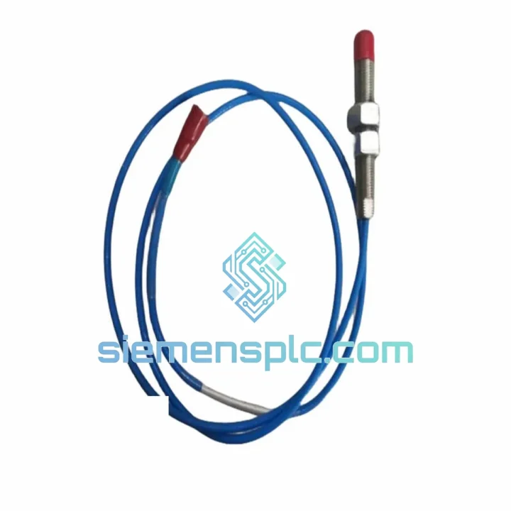
| Connector — Sensor End (A07) | MIL-C-style coaxial plug, gold-contact center pin, locking coupling ring |
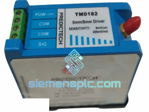
| Connector — Monitor End (B00) | Standard coaxial jack, compatible with TM0182 driver input |
| Armor Grade (C05) | Stainless steel braid over PTFE-insulated inner conductor |
| Outer Jacket | PVC / PTFE composite, oil and chemical resistant |
| Operating Temperature | −40 °C to +125 °C continuous |
| Bend Radius (minimum) | 25 mm (dynamic); 15 mm (static) |
| Tensile Strength | ≥ 150 N axial pull without connector separation |
| Approximate Weight | 70 g |
| Applicable Standards | ISO 10816 / ISO 20816, API 670, IEC 60068 environmental |
| RoHS Compliance | Yes |
| Warranty | 12 months from date of shipment |
An eddy-current proximity measurement loop operates on a fixed-frequency oscillator signal — typically 1 MHz for 8 mm probes — that the driver injects into the probe coil. The probe’s impedance varies as a function of the conductive target’s proximity, and the driver demodulates this impedance change into a DC voltage proportional to gap distance (nominally −200 mV/mil or −7.87 V/mm for standard sensitivity probes). The extension cable sits electrically between the probe coil and the driver’s oscillator output, forming a distributed LC network that directly affects the resonant frequency and sensitivity of the measurement.
The TM0180-A07-B00-C05-D10 addresses three hardware-level failure modes common to generic cable substitutions:
Impedance Mismatch and Reflection Loss: A 50 Ω characteristic impedance, held to ±2 Ω tolerance along the full 5 m run, ensures that the driver’s output impedance sees a matched load. Mismatched cables — even those differing by 10 Ω — introduce standing wave reflections at the 1 MHz carrier frequency that shift the apparent probe sensitivity by 3–8%, producing systematic displacement measurement error that cannot be corrected by gap adjustment alone.
Capacitive Loading and Bandwidth Compression: The cable’s capacitance per metre specification (≤ 100 pF/m) limits total added capacitance to ≤ 500 pF for the 5 m run. Exceeding this threshold shifts the driver’s resonant operating point, compressing the linear measurement range and reducing the usable bandwidth of the displacement signal — a critical concern in high-speed machinery where shaft dynamic runout components above 1× running speed must be resolved accurately.
EMC and Ground Loop Rejection: The stainless steel braid armor (C05) provides a continuous, low-resistance shield from connector to connector. Unlike aluminum foil shields, braided stainless maintains shield continuity under repeated flexing and mechanical vibration — conditions inherent to any cable routed through a machinery skid. The shield is terminated at both connector bodies, providing a Faraday enclosure that attenuates radiated interference from variable-frequency drives, high-current bus bars, and RF sources common in industrial plants. The PTFE dielectric layer between the inner conductor and the braid provides a stable, low-loss insulation medium that does not absorb moisture or degrade at elevated temperatures, preserving the cable’s electrical parameters over its service life.
Connector Metallurgy and Contact Resistance: The A07 sensor-end connector uses a gold-contact center pin with a locking coupling ring. Gold plating (minimum 0.5 µm) prevents oxidation-induced contact resistance increase — a failure mode that manifests as a slow drift in the DC bias voltage of the measurement loop, indistinguishable from actual shaft position change in trend data. The locking ring prevents vibration-induced connector loosening, which would introduce intermittent open-circuit faults that trigger false high-vibration alarms in the monitoring system.
Every PROVIBTECH TM0180-A07-B00-C05-D10 unit supplied through siemensplc.com is sourced through verified industrial distribution channels with full manufacturer traceability. Pre-shipment inspection covers connector seating force, armor continuity (DC resistance < 0.5 Ω end-to-end on shield), and outer jacket integrity. Units are shipped with original PROVIBTECH labeling, batch markings, and suffix identification intact — no relabeling or repackaging that would obscure traceability.
Logistics operations are based in Xiamen, China, with established freight forwarding partnerships covering express air freight (DHL, FedEx, UPS) and sea freight consolidation for volume orders. Typical transit times: 3–5 business days to Southeast Asia and East Asia; 5–8 business days to Europe and the Middle East; 7–12 business days to the Americas. Export documentation including commercial invoice, packing list, and certificate of origin is prepared for each shipment. HS code classification and customs value declaration are handled accurately to prevent clearance delays. For projects requiring multiple cable lengths or complete proximity measurement loop kits, consolidated shipment with a single customs entry reduces landed cost and clearance time.
The 12-month warranty covers manufacturing defects in connector assembly, armor integrity, and dielectric insulation. Warranty claims are processed with replacement unit dispatch within 5 business days of confirmed defect verification, without requiring return of the defective unit for low-value claims.
Email: [email protected]
WhatsApp: +86 18359268345
Web: siemensplc.com
Location: Xiamen, China
© 2026 siemensplc.com. All rights reserved.
We check the full part number, brand, series and visible nameplate information before quotation.
Sales confirms stock path, condition option, quantity and realistic lead time for export dispatch.
DHL, FedEx, UPS or buyer courier arrangements can be reviewed with packing requirements.
Similar brand or category products for fast comparison and multi-item RFQ lists.