Siemens
In Stock OK
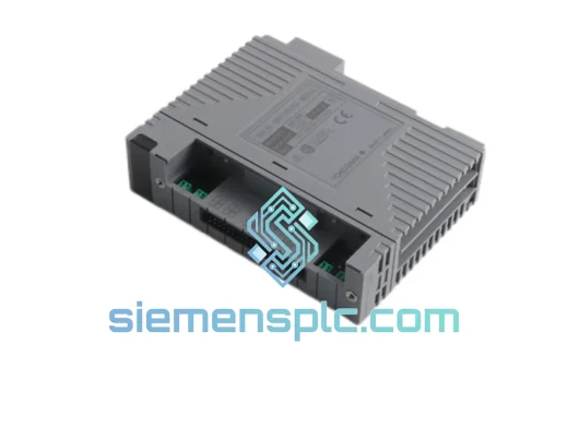
Siemens 1630-2FC Digital Input Module – SIMATIC S7-300 SM 321
Request verified availability, condition, replacement risk review, packing options and courier lead time for 1630-2FC.
BrandSiemens
Part Number1630-2FC
ConditionAvailability Check
Lead TimeRFQ Confirmation
DocumentsDatasheet / photos by RFQ
ShippingExport packing available
Auto-filled RFQ
1630-2FC
Click Request Quote and the part number is inserted into the inquiry form automatically.
- Reply by email: [email protected]
- WhatsApp / Tel: +86 18359268345
- Mon-Sat 9:00-18:00 GMT+8
Procurement Data
Key Product Information
Core fields for model confirmation and RFQ routing. Detailed product narrative remains below.
- Brand
- Siemens
- Primary Part Number
- 1630-2FC
- Product Type
- Digital Input Module
- Series / Family
- SIMATIC S7-300
- Country of Origin
- DE
- Catalog Category
- I/O Modules
- Warranty
- 12 months from date of shipment
Model confirmed for inquiry
1630-2FC
Send quantity, destination and urgency. The RFQ form keeps this part number attached.
Request Quote
Product Overview
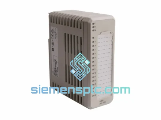
Siemens 1630-2FC SM 321 — 16-Channel 24 V DC Binary Signal Interface for SIMATIC S7-300 Distributed Control Systems
The Siemens 1630-2FC belongs to the SM 321 digital input module series within the SIMATIC S7-300 modular programmable controller platform. Its primary function is to acquire binary field signals — sourced from 24 V DC two-wire sensors, mechanical contacts, proximity detectors, and pushbutton assemblies — and present verified, electrically isolated logic states to the S7-300 CPU’s process image input (PII) table on every scan cycle. The module occupies a 40 mm slot on the S7-300 mounting rail and communicates with the central processing unit exclusively through the P-bus (parallel backplane bus), which operates synchronously with the CPU’s operating cycle clock.
Within a control loop, the 1630-2FC sits at the boundary between the physical process and the programmable logic domain. Field-side signals arrive at the 20-pin front connector, pass through a hardware input filter stage, cross an optocoupler isolation barrier rated at 500 V AC, and are then latched into a 16-bit parallel register by the module’s onboard input ASIC. During the CPU’s process image update phase, this register is transferred atomically across the P-bus into the PII address space assigned to the module during hardware configuration. The result is a consistent, glitch-free snapshot of all 16 field states, available to the user program at the start of each OB1 cycle — or immediately upon interrupt trigger for edge-sensitive channels.
This architecture makes the 1630-2FC suitable for applications where signal integrity and scan-cycle determinism are non-negotiable: conveyor line end-of-travel detection, valve position feedback in batch processing, safety interlock monitoring in machine guarding systems, and binary status acquisition from field junction boxes in distributed panel layouts.
Real-time Stock & RFQ: [email protected] | WhatsApp: +86 18359268345
Technical Parameters
| Parameter | Value |
|---|---|
| Siemens Article Number | 1630-2FC |
| Module Designation | SM 321; DI 16 × DC 24 V |
| Platform | SIMATIC S7-300 |
| Number of Digital Inputs | 16 |
| Rated Input Voltage | 24 V DC |
| Signal 1 Voltage Range | +13 V DC to +30 V DC |
| Signal 0 Voltage Range | −3 V DC to +5 V DC |
| Typical Input Current at Signal 1 | 7 mA |
| Input Resistance | Approx. 3.4 kΩ |
| Galvanic Isolation | 500 V AC (field side vs. logic side), groups of 16 |
| Input Delay Filter (Configurable) | 0.1 / 0.5 / 3 / 15 / 20 ms per channel group |
| Backplane Bus Interface | S7-300 P-bus (parallel, synchronous) |
| Process Image Update | Synchronous with CPU scan cycle (OB1) |
| Diagnostic Interrupt | Supported — configurable in STEP 7 / TIA Portal HW Config |
| Process Interrupt (Edge) | Rising / falling edge, selectable per channel group |
| Current Draw from P-bus (5 V DC) | Max. 60 mA |
| External Supply Voltage Required | None (powered via backplane bus) |
| Operating Temperature (Horizontal) | 0 °C to +60 °C |
| Operating Temperature (Vertical) | 0 °C to +40 °C |
| Storage Temperature | −40 °C to +70 °C |
| Relative Humidity | 10 % to 95 %, non-condensing |
| Degree of Protection | IP20 (EN 60529) |
| Module Dimensions (W × H × D) | 40 mm × 125 mm × 120 mm |
| Approximate Weight | 200 g |
| Mounting Method | S7-300 DIN rail mounting rail, snap-on |
| Front Connector | 20-pin screw or spring-cage type (ordered separately) |
| EMC Immunity Standard | EN 61000-6-2 (Industrial) |
| EMC Emission Standard | EN 61000-6-4 |
| Certifications | CE, UL, cULus, ATEX (zone 2 with appropriate enclosure) |
| Warranty | 12 months from date of shipment |
Hardware Logical Analysis
The 1630-2FC implements a three-stage signal processing chain between the field terminal and the backplane bus register. Understanding each stage is essential for engineers selecting input filter parameters and designing cable layouts in electrically noisy environments.
Stage 1 — Field Interface and Current Limiting: Each of the 16 input terminals connects through a series resistor network (approximately 3.4 kΩ effective impedance) that limits the steady-state input current to approximately 7 mA at 24 V DC. This resistor network simultaneously serves as a first-order RC low-pass filter in conjunction with the parasitic capacitance of the PCB trace, attenuating high-frequency transients above approximately 50 kHz before they reach the optocoupler LED. The network is dimensioned to maintain signal 1 recognition down to 13 V DC, accommodating the voltage drop across long cable runs (up to several hundred meters of 1.5 mm² cross-section cable) without false signal 0 detection.
Stage 2 — Optocoupler Isolation Barrier: The optocoupler stage provides 500 V AC galvanic isolation between the field wiring domain and the logic domain. The LED side of the optocoupler is driven by the field-side current; the phototransistor output feeds directly into the input ASIC on the logic side. The isolation barrier eliminates common-mode voltage interference — a critical design requirement in installations where field devices share a common ground with variable-frequency drives or other power electronics that generate common-mode noise in the range of tens to hundreds of volts. The optocoupler’s inherent propagation delay (typically 0.5 ms to 1 ms) is the dominant contributor to the minimum achievable input filter time; the configurable filter adds additional delay on top of this baseline.
Stage 3 — Input ASIC and Configurable Hardware Filter: The logic-side ASIC implements the configurable debounce filter entirely in hardware logic, independent of the CPU’s firmware. The filter operates as a majority-vote or timer-based debounce circuit: a signal transition is only accepted after the new state has been stable for the configured filter period (0.1 ms, 0.5 ms, 3 ms, 15 ms, or 20 ms). This hardware implementation means the filter latency is deterministic and does not vary with CPU load or communication traffic — a property that firmware-based filters cannot guarantee. The ASIC also manages the interrupt generation logic: when a configured edge event occurs on a process-interrupt-enabled channel group, the ASIC asserts an interrupt request on the P-bus, causing the CPU to suspend OB1 and execute the assigned interrupt OB (OB40 or higher) within the CPU’s interrupt response time.
EMC Design Architecture: The PCB layout separates field-side copper (terminals, current-limiting resistors, optocoupler LED traces) from logic-side copper (ASIC, bus interface, power regulation) using a physical gap and a continuous ground plane layer interposed between the two routing layers. The module housing connects to the S7-300 rack’s functional earth rail through the backplane connector, providing a low-impedance shielding path for capacitively coupled interference. This layout achieves EN 61000-6-2 compliance for 4 kV contact ESD, 2 kV/m radiated field immunity at 80 MHz–1 GHz, and 2 kV fast transient burst on signal lines — without requiring ferrite beads or external suppression components on the field wiring in standard installations.
System Integration Benefits
- Atomic Process Image Snapshot: All 16 channel states are transferred to the CPU’s PII in a single P-bus transaction at the start of each scan cycle. This atomic transfer eliminates the possibility of reading a partially updated input word — a failure mode that affects systems using serial fieldbus I/O with asynchronous update cycles.
- Sub-Millisecond Edge Interrupt Response: With the 0.1 ms filter setting and process interrupt enabled, the 1630-2FC can trigger an interrupt OB within the CPU’s interrupt response time (typically 0.5 ms to 2 ms depending on CPU model and OB1 cycle load), enabling event-driven control sequences for high-speed binary events such as cam switch pulses and encoder index marks.
- Channel-Level Diagnostic Transparency: Wire-break and short-circuit faults are detected at the module level and reported as diagnostic events in the CPU’s diagnostic buffer, accessible via STEP 7 or TIA Portal online diagnostics without requiring a physical site visit or additional diagnostic hardware.
- Engineering Tool Consistency: Hardware configuration, filter parameter assignment, interrupt enable/disable, and diagnostic settings are all managed within the same STEP 7 HW Config or TIA Portal project environment used for the CPU and other S7-300 modules — no separate configuration software, no GSD file import, no proprietary commissioning tool.
- Standardized Mechanical Footprint: The 40 mm width and 20-pin front connector are consistent across the SM 321 family, allowing the 1630-2FC to be replaced with other SM 321 variants (different voltage ratings or channel counts) without modifying the mounting rail, cable duct layout, or front connector wiring — only the hardware configuration in the engineering project requires updating.
- Backplane Bus Power Only: The 1630-2FC draws its logic-side power exclusively from the S7-300 backplane bus (max. 60 mA at 5 V DC). No separate 24 V DC logic supply is required, simplifying the power distribution design and reducing the number of power supply terminals in the control panel.
- Scalable Rack Architecture: Up to 8 signal modules can be mounted per S7-300 rack, and up to 3 expansion racks can be connected via IM 360/361 interface modules, allowing the 1630-2FC to be deployed in distributed rack configurations spanning multiple cabinet sections without changing the programming model.
- Reduced Commissioning Time via Online Force Function: During commissioning, individual input channels can be monitored in real time through the STEP 7 or TIA Portal variable table, and the CPU’s force function allows engineers to override input states for logic testing without disconnecting field wiring — reducing commissioning time on complex interlock sequences.
Quality Assurance & Global Logistics
siemensplc.com operates from Xiamen, China, one of the primary logistics hubs for industrial component distribution in East Asia. All Siemens 1630-2FC units dispatched from our facility are subject to a structured pre-shipment verification protocol before packaging.
Origin and Traceability: Units are sourced through documented supply channels. Each module is inspected against Siemens’ factory identification criteria: holographic authenticity labels, production date codes stamped on the housing, and factory-applied serial number markings. Batch records are retained for traceability in the event of a warranty claim.
Pre-Shipment Inspection: Visual inspection covers housing integrity, connector pin condition, label completeness, and packaging seal status. Where bench test fixtures are available, modules are powered via a test rack to verify backplane bus communication response and LED indicator behavior before dispatch.
Packaging Integrity: Modules are shipped in original Siemens factory cartons with ESD-protective inner packaging. All factory-included accessories — 20-pin front connector (where included), labeling strips, and product documentation — are verified present before sealing.
Export and Customs Documentation: Our Xiamen logistics team prepares a complete export documentation set for every shipment: commercial invoice with HS code classification (HS 8537.10 for programmable controller modules), packing list, certificate of origin (China), and — upon request — a material safety data sheet. This documentation set is formatted to meet customs requirements in the EU, GCC, ASEAN, and North American import markets.
Shipping Carriers and Transit Times: Standard dispatch is via DHL Express, FedEx International Priority, or UPS Worldwide Express, with typical transit times of 3 to 5 business days to Europe, 4 to 7 business days to the Middle East and Southeast Asia, and 5 to 8 business days to North America. Sea freight consolidation is available for pallet-quantity orders. All shipments include a tracking number issued at the time of dispatch and cargo insurance covering the declared value.
Warranty Terms: A 12-month warranty applies from the date of shipment. Defective units are assessed by our technical team upon return; confirmed manufacturing defects result in replacement or credit note issuance within 10 business days of receipt. Warranty does not cover damage from incorrect installation voltage, mechanical impact, or unauthorized modification.
Contact Information
Email: [email protected]
WhatsApp: +86 18359268345
Web: siemensplc.com
Location: Xiamen, China
© 2026 siemensplc.com. All rights reserved.
Ready to quote
[email protected]
Send This Part Number to Sales
RFQ workflow
Quality workflow ->
Confirmation Process
01Model confirmation
We check the full part number, brand, series and visible nameplate information before quotation.
02Availability reply
Sales confirms stock path, condition option, quantity and realistic lead time for export dispatch.
03Packing & courier
DHL, FedEx, UPS or buyer courier arrangements can be reviewed with packing requirements.
Continue sourcing
Browse full catalog ->
Related Automation Parts
Similar brand or category products for fast comparison and multi-item RFQ lists.
Siemens
RFQ Ready
Siemens 6ES7 315-2EH14-0AB0 CPU 315-2 PN/DP Module
SIMATIC S7-300
Origin DE
PLC CPU Module
Siemens
RFQ Ready
Siemens 6ES7315-2EH14-0AB0 CPU 315-2 PN/DP PLC Module
SIMATIC S7-300
Origin DE
PLC CPU Module
Siemens
RFQ Ready
Siemens 6ES7 321-1BL00-0AA0 Digital Input Module
SIMATIC S7-300
Origin DE
PLC Digital Input Module