Siemens
RFQ Ready
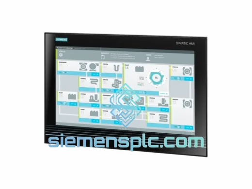
Siemens 6AV7260-5GA10-0BX0 Industrial Panel PC
SIMATIC
Origin DE
Industrial Panel PC
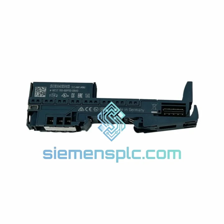
Request verified availability, condition, replacement risk review, packing options and courier lead time for 6ES7193-6BP00-0BA0.
Click Request Quote and the part number is inserted into the inquiry form automatically.
Core fields for model confirmation and RFQ routing. Detailed product narrative remains below.
The Siemens 6ES7193-6BP00-0BA0 is a 15 mm-wide Type A0 base unit within the SIMATIC ET 200SP distributed I/O platform. Designated BU15-P16+A0+2B, it functions as the fixed wiring carrier and backplane bus segment for one I/O module slot. Unlike conventional terminal blocks, this base unit integrates three distinct functional layers into a single 15 mm footprint: field-side push-in terminal wiring (16 terminals), potential group bus distribution (2 configurable groups via color-coded bus bridges), and the backplane electrical interface that transfers I/O data to the plugged module. Understanding these three layers is essential for correct system design and cabinet layout.
In a standard ET 200SP station, the interface module (IM 155-6 PN/2 or similar) communicates with each base unit’s plugged I/O module via the internal backplane bus at a cycle time determined by the PROFINET controller’s configured update rate — typically 1 ms to 4 ms in high-performance applications. The base unit itself is passive in terms of data processing; it provides the physical and electrical continuity of the backplane bus segment, passing the differential bus signals from one slot to the next with no active buffering. This passive architecture means the base unit introduces no additional latency into the I/O scan cycle, and its reliability is governed entirely by mechanical and electrical contact integrity rather than firmware.
Real-time Stock & RFQ: [email protected] | WhatsApp: +86 18359268345
| Order Number (MLFB) | 6ES7193-6BP00-0BA0 |
| Product Family | SIMATIC ET 200SP |
| Base Unit Designation | BU15-P16+A0+2B (Type A0, Light) |
| Slot Width | 15 mm |
| Terminal Type | Push-in (PUSH IN), tool-free insertion |
| Number of Terminals | 16 (field-side) |
| Conductor Cross-Section (Solid) | 0.2 – 1.5 mm² |
| Conductor Cross-Section (Ferrule) | 0.25 – 1.5 mm² |
| Potential Groups | 2 (bus bridge color: light = Group 1) |
| Coding Key | A0 (light-colored, pre-installed) |
| Compatible I/O Module Coding | A0 (standard ET 200SP I/O modules) |
| Mounting | 35 mm DIN rail, snap-on, no tools required |
| Degree of Protection | IP20 (IEC 60529) |
| Operating Temperature | 0 °C to +60 °C |
| Storage Temperature | -40 °C to +70 °C |
| Relative Humidity | 5 % to 95 %, non-condensing |
| Vibration Resistance | 5 – 150 Hz, 1 g (IEC 60068-2-6) |
| Shock Resistance | 15 g / 11 ms (IEC 60068-2-27) |
| Weight (base unit only) | Approx. 30 g |
| Certifications | CE, UL, cULus, ATEX Zone 2, IECEx, KC |
| Country of Origin | Germany |
| Siemens Manual Reference | A5E03576848 (ET 200SP Base Unit Manual) |
| Warranty | 12 months from date of shipment |
Backplane Bus Segment Continuity
The 6ES7193-6BP00-0BA0 carries the ET 200SP internal backplane bus through a gold-plated edge connector on its rear face. This connector mates with the corresponding socket on the plugged I/O module, establishing the data path between the interface module and the field I/O. The bus topology is a daisy-chain segment: each base unit receives the bus from the left neighbor and passes it to the right neighbor through internal copper traces. Contact resistance across the backplane connector is specified at <10 mΩ per pin under rated conditions, ensuring signal integrity across stations with up to 64 module slots.
Potential Group Architecture and Bus Bridge Logic
The two potential groups (2B designation) are implemented via removable bus bridges that clip into the base unit’s top rail. Light-colored bridges (Group 1) distribute 24 VDC supply and 0 V reference across adjacent base units without additional wiring. When a potential group boundary is required — for example, to isolate sensor supply from actuator supply — the bus bridge is interrupted at that slot, and a new group begins. This architecture eliminates the need for separate terminal blocks for power distribution, reducing cabinet wiring density by approximately 30–40% compared to conventional distributed I/O wiring schemes.
A0 Coding Key Mechanical Interlock
The A0 coding key is a molded polycarbonate insert pre-installed in the base unit’s module slot. Its geometry is unique to the A0 designation and physically prevents insertion of I/O modules with incompatible coding keys (B0, C0, D0, etc.). This mechanical interlock operates independently of any software or firmware, providing a hardware-enforced safeguard against module misplacement during maintenance. In multi-potential-group stations where different module types occupy adjacent slots, the coding key system is the primary defense against cross-wiring faults that could damage field devices or corrupt I/O data.
Push-In Terminal Contact Mechanism
Each of the 16 push-in terminals uses a spring-clamp contact mechanism. Solid conductors are inserted directly; ferrule-terminated flexible conductors require a 3 mm screwdriver to depress the release lever. The spring force is calibrated to maintain a contact pressure of 3–5 N across the specified conductor cross-section range (0.2–1.5 mm²), compensating for conductor creep over time without requiring periodic re-torquing. This is a measurable advantage over screw-terminal designs in high-vibration environments such as press lines or compressor rooms, where screw terminals are subject to loosening under cyclic mechanical stress.
EMC Design Considerations
The base unit’s DIN rail mounting clip provides a low-impedance ground path from the base unit housing to the cabinet DIN rail, which is typically bonded to the cabinet PE (protective earth) bus. This ground path shunts high-frequency interference currents induced on field cable shields directly to PE, bypassing the signal terminals. In installations where field cables run parallel to power cables for distances exceeding 1 m, this PE bonding path is the primary EMC mitigation mechanism. The base unit housing is manufactured from glass-fiber-reinforced polyamide with a conductive coating on the DIN rail contact surfaces, maintaining <1 Ω contact resistance to the rail across the operating temperature range.
All units supplied by siemensplc.com are sourced from Siemens-authorized distribution channels and carry original Siemens factory packaging, holographic authenticity labels, and batch codes traceable to Siemens production records. Each shipment undergoes a 100% pre-shipment inspection covering terminal contact integrity, coding key presence and seating, backplane connector pin condition, and label legibility. Units are packed in anti-static bags with foam cushioning, suitable for direct use in ESD-sensitive environments.
Shipments originate from our warehouse in Xiamen, China — a major logistics hub with direct access to DHL Express, FedEx International Priority, and SF Express international services. Standard export documentation (commercial invoice, packing list, certificate of origin) is provided with every shipment. For orders requiring expedited customs clearance, we provide HS code 8538.90 pre-classification documentation and can arrange DDP (Delivered Duty Paid) terms upon request.
Typical transit times: 3–5 business days to Europe and North America via DHL/FedEx express; 5–8 business days to Southeast Asia and the Middle East. Tracking numbers are issued within 24 hours of shipment. All units are covered by a 12-month warranty from the date of shipment, covering manufacturing defects and confirmed authenticity. Warranty claims are processed within 5 business days of receipt of the returned unit.
Email: [email protected]
WhatsApp: +86 18359268345
Web: siemensplc.com
Location: Xiamen, China
© 2026 siemensplc.com. All rights reserved.
We check the full part number, brand, series and visible nameplate information before quotation.
Sales confirms stock path, condition option, quantity and realistic lead time for export dispatch.
DHL, FedEx, UPS or buyer courier arrangements can be reviewed with packing requirements.
Similar brand or category products for fast comparison and multi-item RFQ lists.