Siemens
RFQ Ready
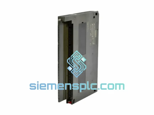
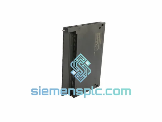
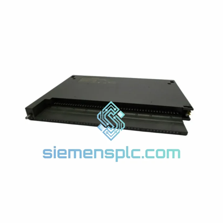
Siemens 6ES7431-1KF00-0AB0 Analog Input Module
SIMATIC S7-400
Origin DE
PLC Analog Input Module
Request verified availability, condition, replacement risk review, packing options and courier lead time for 6ES7421-7BH01-0AB0.
Click Request Quote and the part number is inserted into the inquiry form automatically.
Core fields for model confirmation and RFQ routing. Detailed product narrative remains below.
Real-time Stock & RFQ: [email protected] | WhatsApp: +86 18359268345
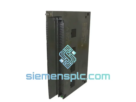
The SM 421 module family occupies the field-signal acquisition layer of the SIMATIC S7-400 rack architecture. Within this family, the 6ES7421-7BH01-0AB0 is distinguished by its per-channel hardware interrupt capability — a design attribute that separates event-driven control logic from the deterministic scan cycle, enabling sub-millisecond response to discrete field events without burdening the CPU’s cyclic program execution. This module is the correct selection for applications where signal latency, diagnostic transparency, and long-term field reliability are primary engineering constraints.
The S7-400 platform operates on a high-speed P-bus (peripheral bus) and C-bus (communication bus) backplane architecture. The SM 421 interfaces exclusively with the P-bus, transferring its 16-channel input image to the CPU’s Process Image Input (PII) table at each scan cycle. When a hardware interrupt condition is detected — configurable per channel for rising edge, falling edge, or both — the module asserts an interrupt request on the backplane, causing the CPU to suspend the current OB1 cycle and execute OB40 (hardware interrupt OB) with a latency typically below 1 ms under normal rack loading. This mechanism is fundamental to applications such as cam-controlled positioning, high-speed counting pre-stages, and time-stamped event logging in power generation or chemical batch processes.
The module’s wire-break detection function operates independently of the scan cycle. Each input channel monitors the field-side current path; a broken conductor causes the channel’s diagnostic status bit to assert, triggering OB82 (diagnostic interrupt OB) and logging a structured diagnostic record readable via SFB 52 (RDREC). This architecture eliminates the need for external field-wiring supervision relays and reduces mean time to repair (MTTR) by providing exact channel-level fault localisation directly within the STEP 7 or TIA Portal diagnostic buffer.
| Order Number (MLFB) | 6ES7421-7BH01-0AB0 |
| Module Designation | SM 421 Digital Input Module |
| Compatible Platform | SIMATIC S7-400 (CR / ER racks) |
| Number of Input Channels | 16 |
| Rated Input Voltage | 24 V DC |
| Permissible Input Voltage Range | 20.4 V DC … 28.8 V DC |
| Signal “1” Threshold | 13 V … 30 V DC |
| Signal “0” Threshold | −30 V … +5 V DC |
| Typical Input Current at Signal “1” | 7 mA |
| Input Filter Delay (Selectable) | 0.1 ms / 0.5 ms / 3 ms / 15 ms (per channel group) |
| Hardware Interrupt | Yes — rising edge, falling edge, or both; configurable per channel |
| Diagnostic Interrupt | Yes — wire-break detection per channel, reported to OB82 |
| Galvanic Isolation | Optocoupler isolation, field side vs. backplane bus |
| Isolation Test Voltage | 500 V AC (field to backplane) |
| Backplane Bus Current Draw | Max. 100 mA at 5 V DC |
| Power Dissipation | Max. 3.5 W |
| Front Connector | 40-pin (screw: 6ES7492-1AL00-0AA0 / spring-cage: 6ES7492-1BL00-0AA0, ordered separately) |
| Module Dimensions (W × H × D) | 25 mm × 290 mm × 210 mm |
| Weight | Approx. 500 g |
| Operating Temperature | 0 °C … +60 °C |
| Storage Temperature | −40 °C … +70 °C |
| Relative Humidity | 10 % … 95 %, non-condensing |
| Degree of Protection | IP 20 |
| EMC Standards | EN 61000-6-2 (immunity) / EN 61000-6-4 (emission) |
| Certifications | CE, UL, cUL, ATEX Zone 2 |
| Warranty | 12 months from dispatch date |
Optocoupler Isolation Architecture
Each of the 16 input channels is individually isolated via a dedicated optocoupler. The LED side of the optocoupler is driven by the field-side 24 V DC signal through a current-limiting resistor network, producing a nominal 7 mA drive current at rated voltage. The phototransistor side interfaces with the module’s internal 5 V DC logic domain. This two-domain architecture provides a galvanic barrier rated at 500 V AC, suppressing common-mode noise, ground potential differences between field cabinets, and transient surge events that would otherwise propagate to the backplane bus and corrupt the CPU’s input image.
Input Filter and Debounce Logic
The selectable input delay (0.1 ms, 0.5 ms, 3 ms, 15 ms) is implemented as a digital filter on the module’s internal ASIC. The filter integrates the optocoupler output over the selected time window before committing a state change to the input image register. This mechanism rejects contact bounce from mechanical switches and relay contacts without requiring external RC filter networks, reducing BOM complexity in field junction boxes. The 0.1 ms setting is appropriate for solid-state proximity sensors; the 15 ms setting is standard for mechanical push-buttons and limit switches in high-vibration environments.
Hardware Interrupt Arbitration
The interrupt detection circuit operates in parallel with the filter logic. When a channel is configured for hardware interrupt, the module monitors the raw (pre-filter) optocoupler output for the configured edge condition. Upon detection, the module asserts an interrupt request on the S7-400 P-bus within one bus cycle (typically 100–200 µs). The CPU’s interrupt arbiter suspends OB1 execution, saves the current program context, and dispatches OB40 with the interrupt status word identifying the source channel. This architecture guarantees that high-priority discrete events — such as emergency stop signals, cam switch pulses, or encoder index marks — are processed with bounded latency independent of the OB1 cycle time.
EMC Design Measures
The module PCB employs a multi-layer stackup with dedicated ground planes separating the field-side and logic-side circuits. Transient voltage suppressors (TVS diodes) are placed at the front connector interface to clamp inductive load switching transients below the optocoupler’s absolute maximum ratings. The module housing is designed to mate with the S7-400 rack’s EMC shielding bus, providing a low-impedance ground path for the module’s chassis. These measures collectively satisfy EN 61000-4-4 (EFT/Burst, 2 kV) and EN 61000-4-5 (surge, 1 kV) immunity requirements without external filtering.
Every unit of the 6ES7421-7BH01-0AB0 supplied through siemensplc.com undergoes a structured pre-shipment verification process before leaving our Xiamen, China facility. Authenticity verification includes visual inspection of the Siemens holographic label, laser-engraved order number and date code cross-referenced against the Siemens product database, and physical inspection of the front connector interface and backplane bus contacts for mechanical integrity. Functional power-on verification is performed where test fixtures are available, confirming LED indicator behaviour and backplane bus enumeration.
Units are dispatched in original Siemens packaging where available. Repackaged units are clearly identified with an accompanying inspection report and certificate of conformity. A 12-month warranty covers verified genuine units against manufacturing defects and premature failure under normal operating conditions. Warranty claims are processed with replacement dispatch within 5 business days of fault confirmation.
Logistics from Xiamen covers all major global destinations. Standard export channels include DHL Express (3–5 business days to Europe and North America), FedEx International Priority, and sea freight consolidation for bulk orders. Export documentation — commercial invoice, packing list, certificate of origin, and ECCN classification — is prepared in compliance with Chinese customs regulations and destination country import requirements. Customers in the EU, USA, Australia, Southeast Asia, and the Middle East are served from existing stock with lead times typically under 72 hours from order confirmation.
Email: [email protected]
WhatsApp: +86 18359268345
Web: siemensplc.com
Location: Xiamen, China
© 2026 siemensplc.com. All rights reserved.
We check the full part number, brand, series and visible nameplate information before quotation.
Sales confirms stock path, condition option, quantity and realistic lead time for export dispatch.
DHL, FedEx, UPS or buyer courier arrangements can be reviewed with packing requirements.
Similar brand or category products for fast comparison and multi-item RFQ lists.