Siemens
In Stock OK
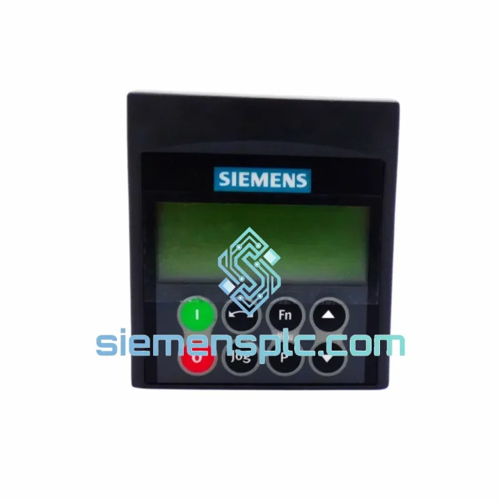
Siemens 6SE6400-0AP00-0AA1 Operator Panel – MICROMASTER 4
Request verified availability, condition, replacement risk review, packing options and courier lead time for 6SE6400-0AP00-0AA1.
BrandSiemens
Part Number6SE6400-0AP00-0AA1
ConditionAvailability Check
Lead TimeRFQ Confirmation
DocumentsDatasheet / photos by RFQ
ShippingExport packing available
Auto-filled RFQ
6SE6400-0AP00-0AA1
Click Request Quote and the part number is inserted into the inquiry form automatically.
- Reply by email: [email protected]
- WhatsApp / Tel: +86 18359268345
- Mon-Sat 9:00-18:00 GMT+8
Procurement Data
Key Product Information
Core fields for model confirmation and RFQ routing. Detailed product narrative remains below.
- Brand
- Siemens
- Primary Part Number
- 6SE6400-0AP00-0AA1
- Product Type
- Operator Panel
- Product Family
- Other series
- Manufacturer
- Siemens AG
- Country of Origin
- DE
- Catalog Category
- HMI Panels
- Operating Temp.
- 0 °C to +50 °C (ambient, drive-mounted)
- Warranty
- 12 months from date of dispatch
Model confirmed for inquiry
6SE6400-0AP00-0AA1
Send quantity, destination and urgency. The RFQ form keeps this part number attached.
Request Quote
Product Overview
Siemens 6SE6400-0AP00-0AA1 Basic Operator Panel — Parameter Interface and Local Control Node for MICROMASTER 4 Variable Frequency Drives
The Siemens 6SE6400-0AP00-0AA1 is the factory-designated Basic Operator Panel (BOP) for the MICROMASTER 4 drive family, covering the MM410, MM420, MM430, and MM440 platform variants. Within the control architecture of a MICROMASTER 4 installation, the BOP occupies the human-machine interface layer: it is the physical node through which a commissioning engineer reads and writes drive parameters, monitors real-time operating values, and acknowledges fault conditions — all without requiring a laptop, STARTER software, or a fieldbus connection. This makes it indispensable during initial drive setup, on-site troubleshooting, and maintenance cycles in facilities where network-based diagnostics are unavailable or impractical.
The panel connects directly to the front-face option slot of any MM4-series drive via a proprietary 10-pin edge connector. Electrical power is drawn entirely from the drive’s internal 5 V logic rail — no external supply, no additional wiring. The mechanical retention is achieved through a snap-fit latch that provides IP20-equivalent protection at the panel-to-drive interface. Once seated, the BOP is recognized by the drive firmware within one power cycle, and the full parameter tree (P0001 through P9999 range) becomes accessible through the five-button keypad.
📩 Real-time Stock & RFQ: [email protected] | WhatsApp: +86 18359268345
Technical Parameters
| Parameter | Specification |
|---|---|
| Part Number | 6SE6400-0AP00-0AA1 |
| Manufacturer | Siemens AG |
| Compatible Drive Series | MICROMASTER 4 — MM410 / MM420 / MM430 / MM440 |
| Panel Classification | Basic Operator Panel (BOP) |
| Display Type | 5-digit, 7-segment LED, red illumination |
| Display Resolution | Numeric values up to ±9999.9; fault codes F0001–F0999 |
| Keypad | 5 tactile keys: ▲ ▼ Fn P RUN/STOP |
| Interface Connector | Proprietary 10-pin edge connector, front-mount |
| Power Supply | Sourced from drive internal 5 V DC logic rail; no external supply |
| Current Draw | ≤ 80 mA from drive logic bus |
| Operating Temperature | 0 °C to +50 °C (ambient, drive-mounted) |
| Storage Temperature | −25 °C to +70 °C |
| Degree of Protection | IP20 (panel face); interface slot protection per drive enclosure rating |
| Weight | Approx. 240 g |
| Country of Origin | Germany |
| Warranty | 12 months from date of dispatch |
Hardware Logical Analysis
The 6SE6400-0AP00-0AA1 operates as a passive parameter terminal relative to the drive’s internal USS (Universal Serial Interface) protocol stack. Communication between the BOP and the MM4 drive CPU occurs over a single-wire, half-duplex serial link embedded in the 10-pin connector. The drive firmware allocates a dedicated USS slave address (address 0) to the front-panel slot, which means the BOP does not compete with external USS master devices on RS-485 terminals — it operates on a physically separate, internally routed bus segment.
The 5-digit LED display is driven by a dedicated segment controller IC on the BOP PCB, which receives pre-formatted display data from the drive CPU via the serial link. This architecture offloads display rendering from the drive processor entirely, ensuring that BOP display refresh does not introduce latency into the drive’s real-time control loop. The drive’s vector control or V/f control cycle (typically 1–4 ms task period on MM4 hardware) remains unaffected by BOP polling activity.
From an EMC standpoint, the BOP PCB incorporates ferrite bead filtering on the power supply lines drawn from the drive bus, suppressing conducted interference in the 1–30 MHz range that is characteristic of IGBT switching transients in the drive’s power stage. The LED display circuitry uses current-limiting resistors sized for stable operation across the full 4.75–5.25 V tolerance band of the drive’s logic rail, preventing display flicker under bus voltage variation during motor acceleration transients.
The keypad debounce logic is implemented in firmware on the BOP’s onboard microcontroller, with a 50 ms debounce window that filters mechanical contact bounce without introducing perceptible input lag for the operator. Parameter write operations are executed as atomic transactions: the BOP transmits a write request frame, the drive CPU validates the value against the parameter’s min/max bounds and access level, and returns an acknowledgment or error code before the BOP updates its display — preventing partial writes that could leave drive parameters in an inconsistent state.
System Integration Benefits
- Zero-dependency commissioning: The BOP enables full drive parameterization without STARTER software, PC connection, or fieldbus infrastructure — reducing commissioning time on sites with restricted IT access or no network connectivity.
- Deterministic fault response: Fault codes are displayed within one drive control cycle (≤ 4 ms) of fault detection, giving maintenance personnel immediate, unambiguous fault identification without navigating software menus.
- Parameter access depth: All MM4 parameters — including expert-level P-parameters and motor data sets — are accessible through the BOP, with no parameter access restrictions compared to the full STARTER software interface.
- Local setpoint override: The BOP can assume frequency setpoint control (MOP — Motorized Potentiometer function) independently of the active command source, enabling manual speed adjustment during process testing without rewiring analog inputs.
- Non-volatile parameter retention: Parameter changes made via BOP are written to the drive’s EEPROM on command (P0971 = 1), ensuring settings persist through power cycles without requiring a PC backup session.
- Drive status transparency: Real-time display of output frequency, output current, DC bus voltage, and motor speed (in selectable engineering units) provides continuous process visibility at the drive enclosure level.
- Alarm pre-warning visibility: The BOP displays active alarm codes (Axxx) alongside fault codes (Fxxx), allowing operators to identify developing conditions before they escalate to drive trip events.
- Hot-swap capability: The BOP can be removed and reinserted while the drive is powered (drive in stopped state), supporting panel swaps during maintenance without requiring a full system shutdown — a practical advantage in continuous-process environments.
- No licensing or activation: The BOP requires no software license, firmware activation key, or registration — it is fully functional immediately upon mechanical installation.
- Interchangeable across MM4 variants: A single BOP unit is mechanically and electrically compatible with all four MM4 drive models (MM410 through MM440), simplifying spare parts inventory management for facilities operating mixed MM4 fleets.
Quality Assurance & Global Logistics
Every 6SE6400-0AP00-0AA1 unit dispatched from siemensplc.com is sourced as genuine Siemens manufacture — original factory production, not refurbished, not cloned, and not relabeled third-party product. Units are stored in anti-static packaging in a climate-controlled warehouse in Xiamen, China, maintaining component integrity from storage through dispatch.
Pre-shipment inspection covers: packaging seal integrity, label authenticity verification against Siemens part number format standards, and physical inspection for connector pin condition and PCB enclosure integrity. Each unit is individually bagged and boxed to IEC 60068-2 transport vibration tolerance standards before handover to the freight carrier.
Logistics from Xiamen reach major industrial hubs on the following typical transit schedules: Southeast Asia 3–5 business days (DHL/FedEx express); Europe 5–7 business days (express air freight); North America 5–8 business days; Middle East and South Asia 4–6 business days. All shipments include tracking numbers issued within 24 hours of dispatch confirmation. Export documentation — commercial invoice, packing list, and certificate of origin — is prepared to customs clearance standards for the destination country.
The 12-month warranty covers manufacturing defects and functional failure under normal operating conditions as defined in Siemens product documentation. Warranty claims are processed with a target response time of 48 hours from receipt of the defective unit.
Contact Information
📧 Email: [email protected]
📱 WhatsApp: +86 18359268345
🌐 Web: siemensplc.com
📍 Location: Xiamen, China
© 2026 siemensplc.com. All rights reserved.
Ready to quote
[email protected]
Send This Part Number to Sales
RFQ workflow
Quality workflow ->
Confirmation Process
01Model confirmation
We check the full part number, brand, series and visible nameplate information before quotation.
02Availability reply
Sales confirms stock path, condition option, quantity and realistic lead time for export dispatch.
03Packing & courier
DHL, FedEx, UPS or buyer courier arrangements can be reviewed with packing requirements.
Continue sourcing
Browse full catalog ->
Related Automation Parts
Similar brand or category products for fast comparison and multi-item RFQ lists.
Siemens
RFQ Ready
Siemens 6AV7240-0HC07-0PA0 Industrial Panel PC Motherboard – SIMATIC IPC477D
SIMATIC
Origin DE
Industrial Panel PC Motherboard