Siemens
In Stock OK
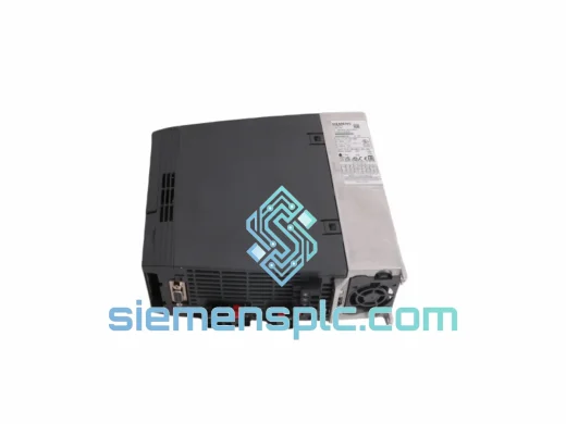
Siemens 6SE6440-2UD24-0BA1 Variable Frequency Drive – MICROMASTER 440
Request verified availability, condition, replacement risk review, packing options and courier lead time for 6SE6440-2UD24-0BA1.
BrandSiemens
Part Number6SE6440-2UD24-0BA1
ConditionAvailability Check
Lead TimeRFQ Confirmation
DocumentsDatasheet / photos by RFQ
ShippingExport packing available
Auto-filled RFQ
6SE6440-2UD24-0BA1
Click Request Quote and the part number is inserted into the inquiry form automatically.
- Reply by email: [email protected]
- WhatsApp / Tel: +86 18359268345
- Mon-Sat 9:00-18:00 GMT+8
Procurement Data
Key Product Information
Core fields for model confirmation and RFQ routing. Detailed product narrative remains below.
- Brand
- Siemens
- Primary Part Number
- 6SE6440-2UD24-0BA1
- Product Type
- Variable Frequency Drive
- Product Family
- Other series
- Country of Origin
- DE
- Catalog Category
- Motor Drives
- Warranty
- 12 months against manufacturing defects
Model confirmed for inquiry
6SE6440-2UD24-0BA1
Send quantity, destination and urgency. The RFQ form keeps this part number attached.
Request Quote
Product Overview
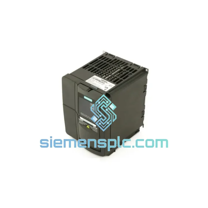
Siemens 6SE6440-2UD24-0BA1 — 4.0 kW Three-Phase AC Drive in the MICROMASTER 440 Platform: Control Loop Architecture and Deployment Context
The 6SE6440-2UD24-0BA1 is a 4.0 kW, 380–480 V three-phase AC variable frequency drive belonging to Siemens’ MICROMASTER 440 (MM440) product family. Within a closed-loop motor control architecture, this unit occupies the position of the primary power conversion and regulation node: it accepts fixed-frequency mains input, rectifies it to an intermediate DC bus, and reconstructs a variable-voltage, variable-frequency (VVVF) output through an IGBT-based inverter stage. The output frequency range extends from 0 to 650 Hz, which accommodates not only standard induction motors but also high-speed spindle drives operating well above the 50/60 Hz utility band.
The MM440 platform implements three distinct control modes selectable via parameter P1300: linear V/f characteristic (suitable for centrifugal pump and fan loads with quadratic torque curves), flux current control (FCC) for improved low-speed torque without encoder feedback, and closed-loop vector control (VC) when a pulse encoder is connected to the optional encoder module. In FCC mode, the drive continuously estimates rotor flux magnitude using a mathematical motor model derived from stator resistance, leakage inductance, and magnetizing inductance values entered during motor commissioning (P0304–P0350 parameter block). This eliminates the need for a tachometer in the majority of variable-torque applications while maintaining speed regulation accuracy within ±0.5% of rated speed across a 1:100 speed range.
The DC bus voltage is maintained at approximately 540 V DC under nominal 400 V AC input. The braking chopper threshold activates at 774 V DC, at which point an external braking resistor (connected to terminals DC+/B+) dissipates regenerative energy from decelerating loads. For applications with frequent or high-inertia braking cycles — hoists, centrifuges, winding machines — the braking resistor selection must account for peak power dissipation and duty cycle to prevent thermal overload of the resistor element.
The drive’s overload capacity is rated at 150% of nominal output current for 60 seconds and 200% for 3 seconds, enabling it to handle motor starting transients without tripping on overcurrent fault F0001. The kinetic buffering function (P1240) allows the drive to ride through mains supply interruptions of up to several hundred milliseconds by reducing output frequency to recover energy from the rotating load inertia, maintaining the DC bus above the undervoltage trip threshold (P2182).
Six programmable digital inputs (DIN1–DIN6, terminals 5–10) accept 24 V DC PNP or NPN signals, configurable for functions including run/stop, direction reversal, fault acknowledgment, fixed frequency selection (P1001–P1015 setpoint table), and external fault injection. Two analog inputs (AI1: 0–10 V / 0–20 mA; AI2: 0–10 V / 0–20 mA / -10 to +10 V) accept speed reference signals from PLCs, DCS analog output cards, or process controllers. Three relay outputs (DO1–DO3) and two analog outputs (AO1, AO2: 0–20 mA) provide status and process variable feedback to supervisory systems. The USS protocol interface on RS-485 (terminals 14–15) supports multi-drop networks of up to 31 drives on a single segment, with baud rates up to 57.6 kbps and a minimum cycle time of approximately 10 ms per drive at 19.2 kbps.
Frame size C housing (275 × 140 × 195 mm, approximately 4.0 kg) uses forced-air cooling with an internal fan drawing ambient air through the bottom inlet and exhausting through the top. Minimum clearances of 100 mm above and below the unit must be maintained for adequate airflow. The IP20 enclosure rating requires installation inside a control cabinet with appropriate ingress protection for the operating environment. Operating ambient temperature range is −10 °C to +50 °C; above 40 °C, output current must be derated by 1.5% per degree Celsius to prevent junction temperature exceedance in the IGBT modules.
Real-time Stock & RFQ: [email protected] | WhatsApp: +86 18359268345
Technical Parameters
| Part Number | 6SE6440-2UD24-0BA1 |
| Brand | Siemens |
| Series | MICROMASTER 440 (MM440) |
| Rated Output Power | 4.0 kW (5.4 HP) |
| Input Voltage | 380–480 V AC, 3-Phase (±10%) |
| Output Voltage | 0–480 V AC, 3-Phase |
| Input Frequency | 47–63 Hz |
| Output Frequency Range | 0–650 Hz |
| Rated Input Current | 10.2 A |
| Rated Output Current | 8.5 A |
| Overload Capacity | 150% / 60 s; 200% / 3 s |
| DC Bus Voltage (nominal) | ~540 V DC |
| Braking Chopper Threshold | 774 V DC |
| Control Modes | V/f linear, Flux Current Control (FCC), Closed-loop Vector (VC) |
| Speed Regulation Accuracy (FCC) | ±0.5% rated speed, 1:100 speed range |
| Digital Inputs | 6 × 24 V DC (PNP/NPN selectable) |
| Analog Inputs | 2 × (0–10 V / 0–20 mA / ±10 V) |
| Digital Outputs | 3 × relay outputs |
| Analog Outputs | 2 × 0–20 mA |
| Communication | USS / RS-485 (standard); PROFIBUS-DP, DeviceNet (optional modules) |
| Protection Class | IP20 |
| Cooling | Forced air, internal fan |
| Ambient Temperature | −10 °C to +50 °C (derate above 40 °C) |
| Frame Size | C — 275 × 140 × 195 mm |
| Weight | ~4.0 kg |
| Certifications | CE (LVD 2014/35/EU, EMC 2014/30/EU), UL, cUL, C-Tick, RoHS |
| Country of Origin | Germany |
| Warranty | 12 months against manufacturing defects |
Hardware Logical Analysis
IGBT Inverter Stage and PWM Modulation: The output stage uses six IGBT switches arranged in a three-phase bridge topology. The pulse-width modulation (PWM) carrier frequency is adjustable from 2 kHz to 16 kHz via parameter P1800. Higher carrier frequencies reduce audible motor noise but increase switching losses in the IGBTs and capacitive leakage current in long motor cables. For cable runs exceeding 50 m, Siemens recommends reducing the carrier frequency to 4 kHz or installing an output dU/dt filter to limit voltage rise rates (dU/dt) at the motor terminals, which can otherwise exceed 1000 V/μs and stress motor winding insulation.
EMC Design and Conducted Emission Suppression: The 6SE6440-2UD24-0BA1 (suffix -0BA1) does not include an integrated EMC line filter; this variant is intended for use with an external Class A or Class B filter selected according to the installation environment and cable length. The internal DC bus capacitor bank provides high-frequency decoupling between the rectifier and inverter stages. Common-mode chokes on the output phase conductors attenuate high-frequency ground currents that would otherwise couple into adjacent signal wiring. For installations requiring EN 61800-3 Category C2 compliance, the external filter 6SE6440-2UC24-0BA1 (filter-integrated variant) or a separately mounted Siemens line filter must be specified.
Motor Model and Flux Estimation: During the automatic motor identification routine (P1910 = 1), the drive injects a series of DC and AC test signals into the motor windings at standstill to measure stator resistance (R1) and leakage inductance (Lσ). These values populate the internal equivalent circuit model used by the FCC algorithm to compute instantaneous rotor flux angle and magnitude. The accuracy of this model directly determines torque linearity at low speeds; errors in R1 greater than 10% of the nominal value produce proportional torque ripple at frequencies below 5 Hz output.
Kinetic Buffering and Ride-Through Logic: The kinetic buffering function monitors DC bus voltage at a 1 ms sampling interval. When bus voltage drops below the configurable threshold (P1245), the drive reduces output frequency at a controlled rate, extracting kinetic energy from the load inertia to sustain the bus. The minimum sustainable bus voltage before IGBT gate drive loss is approximately 430 V DC. This mechanism is particularly effective in fan and pump applications where load inertia is high relative to friction losses, enabling ride-through of supply dips lasting 200–500 ms without motor demagnetization or speed loss exceeding 5%.
Fault Diagnostics Architecture: The drive maintains an 8-entry fault history buffer (r0947–r0949 parameter group) storing fault code, fault value, and timestamp referenced to the drive’s internal operating hour counter. Fault codes are structured in a hierarchical scheme: F-codes indicate faults requiring acknowledgment before restart; A-codes indicate alarms that log without stopping the drive. The BOP (Basic Operator Panel) or AOP (Advanced Operator Panel) displays fault codes in real time; via USS or PROFIBUS, the fault register is accessible as a process data word for integration into SCADA alarm management systems.
System Integration Benefits
- Deterministic speed reference processing: Analog speed reference signals are sampled at 2 ms intervals by the internal ADC, and the resulting setpoint is applied to the ramp function generator within the same 2 ms task cycle, ensuring predictable response latency for closed-loop process controllers.
- Multi-drive USS network coordination: Up to 31 drives share a single RS-485 segment. The USS master (typically a Siemens S7 PLC with CP 340/341 module) polls each drive sequentially; at 19.2 kbps with 4-word process data, the per-drive cycle time is approximately 10 ms, sufficient for coordinated multi-axis speed control in conveyor and web-handling systems.
- PROFIBUS-DP integration via optional CB15 module: With the PROFIBUS option board installed, the drive appears as a standard DP slave with a configurable GSD file. Process data exchange (speed setpoint, control word, actual speed, status word) occurs within the DP cycle time of the master PLC, typically 1–5 ms in a 12 Mbps network, enabling tight synchronization with other field devices.
- PID process controller with feedforward: The internal PID controller (P2200–P2295 parameter block) accepts a process variable from AI1 or AI2 and computes a speed correction output. A feedforward input from a second analog channel allows compensation for measurable disturbances (e.g., inlet pressure variation in pump systems) before they propagate to the controlled variable, reducing steady-state error and overshoot.
- Fixed frequency setpoint table for deterministic step changes: Fifteen fixed frequency setpoints (P1001–P1015) are selectable via binary combinations of DIN inputs, enabling the drive to switch between predefined operating points in under 10 ms without PLC analog output update latency — useful in multi-speed conveyor indexing and batch process sequencing.
- Thermal model and motor protection: The drive computes a continuous I²t thermal model of the connected motor (P0610–P0614), issuing alarm A0511 at 80% thermal capacity and tripping on F0011 at 100%. This eliminates the need for a separate motor thermistor relay in many installations, reducing panel wiring complexity and component count.
- Automatic restart after fault: Parameter P1210 configures the drive to attempt automatic restart after specified fault classes (undervoltage, overvoltage, overcurrent) with a programmable delay and retry count. In unattended pump stations or remote installations, this reduces downtime from transient supply disturbances without requiring operator intervention.
- Diagnostic transparency via analog output mirroring: AO1 and AO2 can be configured to output any internal process variable — actual output frequency, output current, DC bus voltage, motor thermal load percentage — as a 0–20 mA signal readable by a PLC analog input or panel meter, providing continuous process visibility without fieldbus communication overhead.
Quality Assurance & Global Logistics
Every Siemens 6SE6440-2UD24-0BA1 unit supplied by siemensplc.com is sourced through verified industrial supply channels and subjected to pre-shipment inspection covering serial number label integrity, housing condition, connector pin alignment, and power-on self-test confirmation. Units are dispatched from our warehouse in Xiamen, China — a major export hub with direct access to international freight carriers including DHL Express, FedEx International Priority, UPS Worldwide Express, and SF Express for regional Asia-Pacific delivery.
Standard in-stock units ship within 1–3 business days of order confirmation. Export documentation — commercial invoice, packing list, and certificate of origin — is prepared for each shipment. HS Code 8504.40 applies to this product class for customs classification purposes. For orders of 5 or more units, volume pricing and consolidated freight options are available; contact [email protected] with quantity and delivery destination for a formal quotation.
A 12-month warranty against manufacturing defects is provided on all units. Dead-on-arrival (DOA) claims are processed within 7 business days of delivery confirmation. Replacement or credit is issued upon return of the defective unit with the original serial number label intact. Technical support for commissioning, parameter configuration, and fault diagnosis is available via email and WhatsApp throughout the warranty period.
The MM440 series carries CE marking under the EU Low Voltage Directive (2014/35/EU) and EMC Directive (2014/30/EU), UL/cUL listing for North American markets, C-Tick compliance for Australia and New Zealand, and RoHS conformity. All compliance documentation is available on request.
Contact Information
Email: [email protected]
WhatsApp: +86 18359268345
Web: siemensplc.com
Location: Xiamen, China
© 2026 siemensplc.com. All rights reserved.
Ready to quote
[email protected]
Send This Part Number to Sales
RFQ workflow
Quality workflow ->
Confirmation Process
01Model confirmation
We check the full part number, brand, series and visible nameplate information before quotation.
02Availability reply
Sales confirms stock path, condition option, quantity and realistic lead time for export dispatch.
03Packing & courier
DHL, FedEx, UPS or buyer courier arrangements can be reviewed with packing requirements.
Continue sourcing
Browse full catalog ->
Related Automation Parts
Similar brand or category products for fast comparison and multi-item RFQ lists.
Siemens
RFQ Ready
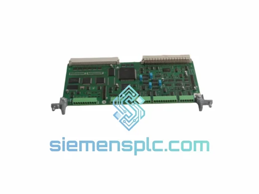
Siemens 6SN1118-0DK23-0AA2 Closed-Loop Control Card
SIMODRIVE
Origin DE
PLC / Drive Control Module
Siemens
RFQ Ready
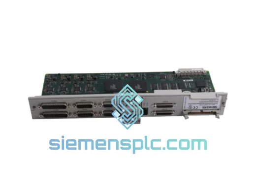
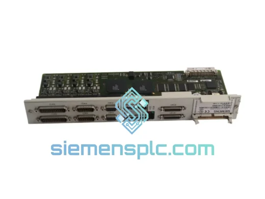
Siemens 6SN1118-0DK23-0AA1 Digital Control Module
SIMODRIVE
Origin DE
PLC & Drive Control Module
Siemens
RFQ Ready
Siemens 6SL3210-1KE18-8UP1 AC Drive Power Module
SINAMICS
Origin DE
AC Drive Power Module