Siemens
In Stock OK
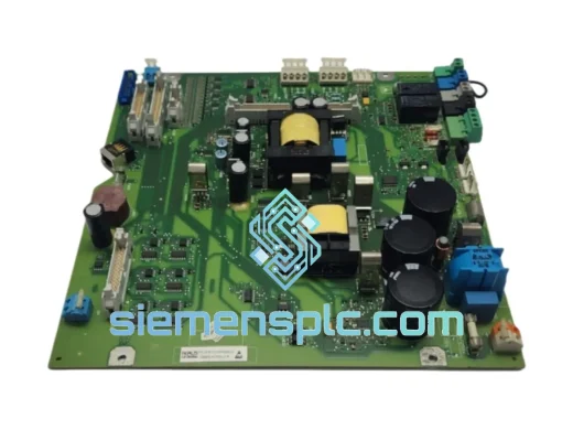
Siemens C98043-A7002-L4-12 Thyristor Firing Control Board – SIMOREG DC Master
Request verified availability, condition, replacement risk review, packing options and courier lead time for C98043-A7002-L4-12.
BrandSiemens
Part NumberC98043-A7002-L4-12
ConditionAvailability Check
Lead TimeRFQ Confirmation
DocumentsDatasheet / photos by RFQ
ShippingExport packing available
Auto-filled RFQ
C98043-A7002-L4-12
Click Request Quote and the part number is inserted into the inquiry form automatically.
- Reply by email: [email protected]
- WhatsApp / Tel: +86 18359268345
- Mon-Sat 9:00-18:00 GMT+8
Procurement Data
Key Product Information
Core fields for model confirmation and RFQ routing. Detailed product narrative remains below.
- Brand
- Siemens
- Primary Part Number
- C98043-A7002-L4-12
- Product Type
- Thyristor Firing Control Board
- Series / Family
- SIMOREG
- Manufacturer
- Siemens AG
- Country of Origin
- DE
- Catalog Category
- Motor Drives
- Warranty
- 12 months from shipment date — manufacturing defects under normal operating conditions
Model confirmed for inquiry
C98043-A7002-L4-12
Send quantity, destination and urgency. The RFQ form keeps this part number attached.
Request Quote
Product Overview
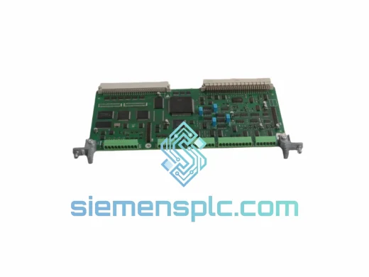
Siemens C98043-A7002-L4-12: Phase-Synchronized Thyristor Gate Drive and Auxiliary Voltage Regulation for SIMOREG DC Master Converter Platforms
The C98043-A7002-L4-12 is a dual-function printed circuit assembly manufactured by Siemens AG for deployment within the SIMOREG DC Master drive family, covering converter frames in the 6RA70 and 6RA24 series. Its two primary responsibilities — generating phase-referenced gate pulses for the six-pulse SCR bridge and supplying regulated auxiliary DC voltages to the drive’s control and measurement subsystems — are implemented on a single four-layer PCB. This integration is architecturally deliberate: the firing angle computation executed on the Central Unit Drive (CUD) board depends on armature current and DC bus voltage measurements whose accuracy is directly determined by the quality of the auxiliary supply rails produced by this board. Separating these functions across two boards would introduce connector impedance and propagation delay between the supply source and the measurement circuits it powers, degrading the signal-to-noise ratio at the CUD’s analog input stage.
Within a six-pulse thyristor rectifier, armature voltage is controlled by advancing or retarding the firing angle — the phase delay between the AC supply zero-crossing and the gate pulse delivered to each SCR. At firing angles below 30°, the converter operates in the continuous conduction region where commutation overlap is minimal and armature current ripple is governed primarily by the DC link inductance. As firing angle increases toward 90° and beyond into the inverting region, commutation overlap grows and the risk of commutation failure — caused by insufficient line voltage to complete current transfer between outgoing and incoming thyristors — increases. The C98043-A7002-L4-12 manages this risk by maintaining firing angle accuracy to ±0.1° across the full operating range, a tolerance that keeps commutation margin within the safety boundary defined in the SIMOREG DC Master application manual for armature currents up to 2000 A DC.
For plant engineers managing DC drive fleets in steel processing, mine winding, rubber extrusion, or large-format printing applications, the C98043-A7002-L4-12 is the board most commonly associated with fault codes indicating armature current instability, auxiliary undervoltage, or loss of firing synchronization. A verified spare held on-site eliminates the procurement lead time — typically four to eight weeks for new Siemens drive components through standard distribution channels — and avoids the full recommissioning cycle that follows a complete drive replacement.
Real-time Stock & RFQ: [email protected] | WhatsApp: +86 18359268345
Technical Parameters
| Part Number | C98043-A7002-L4-12 |
| Manufacturer | Siemens AG |
| Origin | Germany |
| Compatible Drive Series | SIMOREG DC Master — 6RA70, 6RA24 |
| Board Function | Six-pulse SCR gate drive generation + auxiliary DC voltage regulation |
| AC Reference Input Voltage | 3AC 380–575 V, 50/60 Hz (frame-dependent) |
| Maximum Armature Current Coverage | Up to 2000 A DC (drive frame-dependent) |
| Firing Angle Accuracy | ±0.1° across full armature current range |
| Supply Frequency Tracking Range | ±2 Hz from nominal (PLL-based synchronization) |
| Auxiliary Output — Logic Rail | +24 VDC, linear regulated |
| Auxiliary Output — Analog Rails | ±15 VDC, linear regulated |
| Auxiliary Rail Ripple | <5 mV peak-to-peak at rated load |
| Gate Isolation Method | Pulse transformer — galvanic isolation, control-to-SCR gate |
| Current Feedback Resistor TC | ≤50 ppm/°C (metal-film network) |
| PCB Layer Count | 4-layer with dedicated analog and power ground planes |
| Surface Protection | Acrylic conformal coating, IPC-CC-830 compliant |
| Operating Ambient Temperature | 0 °C to +40 °C (derate per Siemens thermal curve above 40 °C) |
| Storage Temperature | −25 °C to +70 °C |
| Relative Humidity | 5% to 95% RH, non-condensing |
| Enclosure Rating | IP00 (board-level; installed within IP-rated drive enclosure) |
| Regulatory Compliance | CE, UL (drive system level) |
| Unit Weight | 740 g |
| Warranty | 12 months from shipment date — manufacturing defects under normal operating conditions |
Hardware Logical Analysis
The gate drive section of the C98043-A7002-L4-12 derives its timing reference from a three-phase zero-crossing detection circuit. Each phase of the AC supply is attenuated through a precision resistive divider to a safe signal level, then fed into a high-speed comparator whose output transitions at each voltage zero-crossing. These transitions clock a phase-locked loop whose voltage-controlled oscillator is tuned to track the supply fundamental at 50 or 60 Hz. The PLL output is divided and phase-shifted by a digital counter chain to produce six equally spaced timing references, each corresponding to the natural commutation point of one thyristor in the bridge. The firing angle command — an analog voltage delivered from the CUD board — is converted to a time delay relative to the nearest natural commutation point by a voltage-to-time converter circuit. The resulting delayed pulse triggers a gate drive amplifier whose output is coupled through a pulse transformer to the thyristor gate-cathode terminal.
The pulse transformer provides galvanic isolation between the gate drive circuit and the thyristor power terminals. During the blocking interval, the thyristor cathode sits at a potential that swings through the full DC bus voltage relative to the control circuit common. Without transformer isolation, this potential difference would drive common-mode current through any direct connection between the gate drive output and the control board ground, injecting noise into the armature current measurement path. The transformer’s leakage inductance also limits the rate of rise of gate current, preventing the gate junction from being driven into avalanche by excessively fast pulse edges — a failure mode that produces latent gate degradation rather than immediate device failure, making it difficult to diagnose in the field.
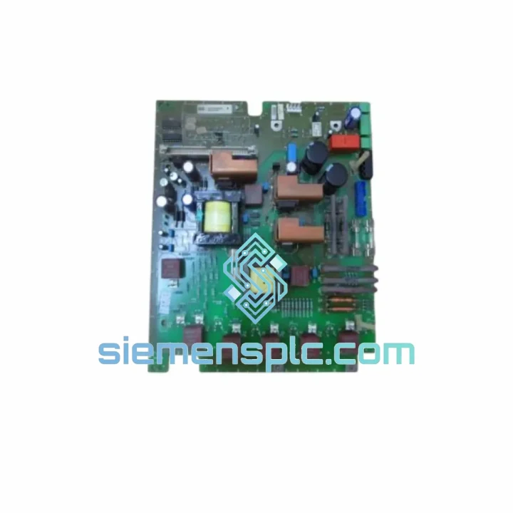
The auxiliary power supply uses a linear regulation topology rather than a switching converter. This choice is driven by the electromagnetic environment inside a thyristor converter cabinet. SCR commutation events generate dV/dt transients on the DC bus that can exceed 500 V/µs. A switching-mode supply operating at 50–200 kHz would generate conducted emissions at its switching frequency and harmonics, which couple onto the ±15 VDC analog rails through parasitic capacitance in the transformer and output filter. These emissions appear as noise at the CUD’s analog-to-digital converter inputs, reducing effective resolution at low armature current setpoints where the signal amplitude is small relative to the noise floor. Linear regulation eliminates the switching noise source entirely. The total auxiliary power budget of the board is below 15 W, making the thermal penalty of linear regulation negligible relative to the drive’s total heat dissipation.
EMC hardening at the board level includes ferrite bead series elements on all gate pulse output lines to suppress high-frequency ringing at pulse edges, transient voltage suppressor diode arrays at each external connector interface to clamp ESD and surge transients, and the four-layer PCB stack-up with separated analog and power ground planes. The ground plane separation prevents commutation-induced ground bounce — a transient shift in ground potential caused by high di/dt in the gate drive return current — from coupling into the armature current feedback node. If this coupling is not suppressed, the current controller on the CUD board interprets the ground bounce as a measurement error and generates a corrective firing angle adjustment that reinforces rather than corrects the disturbance, potentially initiating a current runaway condition.
System Integration Benefits
- Deterministic Firing Angle Accuracy: PLL synchronization maintains ±0.1° firing angle precision across ±2 Hz supply frequency variation, keeping armature voltage ripple within motor insulation stress limits across the full speed range without requiring manual recalibration after grid disturbances.
- Galvanic Isolation of Gate Drive Outputs: Pulse transformer coupling prevents high-voltage transients at the thyristor terminals from propagating into the CUD control domain, protecting the drive’s digital signal processor and analog measurement circuits from commutation-induced overvoltage events.
- Low-Noise Analog Supply Architecture: Linear-regulated ±15 VDC rails with <5 mV ripple preserve the full dynamic range of the CUD’s 12-bit ADC inputs, ensuring current controller resolution is not degraded by supply noise at partial-load operating points where armature current feedback amplitude is low.
- Temperature-Stable Current Feedback: Metal-film resistor divider network with ≤50 ppm/°C coefficient maintains current measurement accuracy as cabinet ambient temperature rises during a production shift, preventing steady-state torque errors that accumulate over time in thermally loaded installations.
- Drop-In Connector Compatibility: Board connector pinout, signal levels, and interface impedances conform to the SIMOREG DC Master hardware specification for 6RA70 and 6RA24 frames, enabling replacement without firmware parameter modification in the majority of installed drive configurations.
- Field-Accessible Diagnostic Test Points: Dedicated measurement nodes for DC bus voltage feedback, gate pulse timing, and auxiliary rail voltages allow board-level fault isolation using standard oscilloscope and multimeter equipment, without requiring drive disassembly or proprietary Siemens diagnostic hardware.
- Industrial-Grade Conformal Coating: IPC-CC-830 acrylic coating resists condensation, conductive particulate from machining and grinding operations, and mild solvent vapors, extending service life in paper mill, cement plant, and chemical processing environments where airborne contamination is a chronic maintenance factor.
- Multi-Frame Spare Coverage: The L4-12 revision is compatible across multiple 6RA70 frame sizes, allowing a single board variant to serve as a common spare for a mixed fleet of drive ratings and reducing the number of unique part numbers a maintenance department must manage in its spare parts inventory.
- Rapid Drive Restoration: Board-level swap restores drive operability within two to four hours of fault isolation. Full drive procurement and recommissioning requires four to eight weeks — a timeline that is operationally unacceptable in continuous-process industries where unplanned downtime costs are measured in thousands of dollars per hour.
- ESD-Safe Transit Packaging: Each unit is individually sealed in a static-dissipative bag, cushioned in a foam-lined carton with desiccant, and labeled with part number and date code, maintaining board integrity through air freight handling, customs inspection, and warehouse storage prior to installation.
Quality Assurance & Global Logistics
Each C98043-A7002-L4-12 unit dispatched from our Xiamen warehouse is a genuine Siemens AG manufactured assembly. Sourcing channels include authorized distributors, certified MRO suppliers, and decommissioned OEM equipment with traceable service histories. Pre-shipment inspection covers physical examination of the PCB surface and connector bodies for mechanical damage, continuity verification at gate drive output connectors, auxiliary rail voltage measurement under representative load conditions, and date code cross-reference against Siemens manufacturing records where documentation is available. A certificate of conformity is issued with each shipment upon request.
Xiamen is one of southern China’s primary international air cargo hubs, with direct access to DHL Express, FedEx International Priority, and UPS Worldwide Express services. Standard transit times are three to five business days to Western Europe and North America, and two to three business days to Southeast Asia and Australia. Sea freight consolidation is available for multi-unit orders where air freight cost is a constraint. All export documentation — commercial invoice, packing list, certificate of origin, and material safety data sheet where applicable — is prepared in-house and reviewed before dispatch. HS code classification support is provided for destinations with complex import duty structures, including the EU, India, and Brazil.
The 12-month warranty covers manufacturing defects and functional failures occurring under normal operating conditions as defined in the Siemens SIMOREG DC Master installation manual. Warranty claims are acknowledged within 48 hours of defective unit receipt at our facility. Where replacement stock is available, a replacement unit is dispatched within 24 hours of claim approval to minimize production downtime for warranty-covered failures.
Contact Information
Email: [email protected]
WhatsApp: +86 18359268345
Web: siemensplc.com
Location: Xiamen, China
© 2026 siemensplc.com. All rights reserved.
Ready to quote
[email protected]
Send This Part Number to Sales
RFQ workflow
Quality workflow ->
Confirmation Process
01Model confirmation
We check the full part number, brand, series and visible nameplate information before quotation.
02Availability reply
Sales confirms stock path, condition option, quantity and realistic lead time for export dispatch.
03Packing & courier
DHL, FedEx, UPS or buyer courier arrangements can be reviewed with packing requirements.
Continue sourcing
Browse full catalog ->
Related Automation Parts
Similar brand or category products for fast comparison and multi-item RFQ lists.
Siemens
RFQ Ready
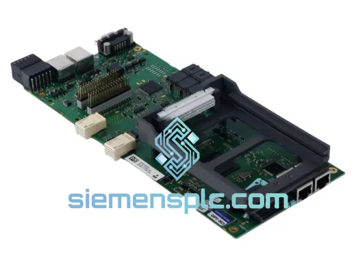
Siemens C98043-A7125-L100 Drive Control Board
SIMOREG
Origin DE
Drive Control Board
Siemens
RFQ Ready
Siemens C98043-A7100-L103 6RY1803-0AA20-0AA1 Thyristor Firing Board
SIMOREG
Origin DE
Thyristor Firing Control Board
Siemens
RFQ Ready
Siemens C98043-A7117-L1 Power Supply Module – SIMOREG DC Master
SIMOREG
Origin DE
Power Supply Module