Siemens
In Stock OK
Siemens PN-184930 Inverter Board – IGBT Power Conversion Module
Request verified availability, condition, replacement risk review, packing options and courier lead time for PN-184930.
BrandSiemens
Part NumberPN-184930
ConditionAvailability Check
Lead TimeRFQ Confirmation
DocumentsDatasheet / photos by RFQ
ShippingExport packing available
Auto-filled RFQ
PN-184930
Click Request Quote and the part number is inserted into the inquiry form automatically.
- Reply by email: [email protected]
- WhatsApp / Tel: +86 18359268345
- Mon-Sat 9:00-18:00 GMT+8
Procurement Data
Key Product Information
Core fields for model confirmation and RFQ routing. Detailed product narrative remains below.
- Brand
- Siemens
- Primary Part Number
- PN-184930
- Product Type
- Inverter Board
- Product Family
- Other series
- Country of Origin
- DE
- Catalog Category
- Motor Drives
- Humidity
- 5% to 95% RH, non-condensing
- Warranty
- 12 months from date of dispatch
- Compliance
- CE, RoHS 2, IEC 61800-5-1, IEC 62477-1
Model confirmed for inquiry
PN-184930
Send quantity, destination and urgency. The RFQ form keeps this part number attached.
Request Quote
Product Overview
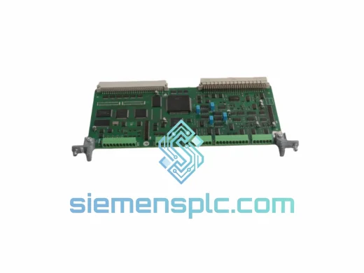
Siemens PN-184930 IGBT Inverter Power Board — Core Power Stage for Industrial Variable-Speed Drive Systems
The Siemens PN-184930 is a dedicated IGBT-based inverter power board engineered for deployment within industrial variable-frequency drive (VFD) assemblies, servo amplifier power stages, and regenerative motion control platforms. As the DC-to-AC conversion nucleus of a drive system, this board governs the switching sequence of the insulated-gate bipolar transistor (IGBT) bridge, translating the intermediate DC bus voltage into a precisely modulated three-phase AC output. Its role in the control loop is not peripheral — it is the final power-stage executor of every velocity, torque, and position command issued by the upstream CPU or motion controller.
In a standard drive architecture, the PN-184930 sits between the DC bus capacitor bank and the motor terminals. The control board generates PWM (pulse-width modulation) signals — typically at switching frequencies between 2 kHz and 16 kHz — which are passed through gate driver circuitry to the IGBT bridge on this board. The PN-184930 then synthesizes the variable-frequency, variable-voltage AC waveform that determines motor shaft speed and torque output. Any degradation in this board’s switching fidelity directly translates to motor instability, elevated harmonic distortion, and thermal stress on the motor windings.
Real-time Stock & RFQ: [email protected] | WhatsApp: +86 18359268345
Technical Parameters
| Part Number | PN-184930 |
| Brand | Siemens |
| Series | SINAMICS / SIMODRIVE Compatible Inverter Stage |
| Component Classification | IGBT Inverter Power Board (DC/AC Conversion PCB Assembly) |
| Power Topology | Three-phase full-bridge IGBT inverter (6-switch topology) |
| Switching Device | IGBT modules (co-packaged with freewheeling diodes) |
| PWM Switching Frequency | 2 kHz – 16 kHz (drive-dependent, set via control board parameters) |
| DC Bus Input Voltage | Nominal 540–600 VDC (for 400 VAC input drives); verify per drive series datasheet |
| Gate Drive Isolation | Optocoupler-based galvanic isolation per IGBT switch leg |
| Thermal Interface | Direct heatsink mounting with thermal compound interface; forced-air or liquid cooling compatible |
| Ambient Operating Temperature | 0°C to +55°C (derate above 40°C per IEC 61800-5-1) |
| Storage Temperature | -25°C to +70°C |
| Humidity | 5% to 95% RH, non-condensing |
| Pollution Degree | PD2 (IEC 60664-1) |
| Overvoltage Category | Category III |
| PCB Standard | IPC Class 2 / Class 3 (industrial-grade laminate, conformal coating optional) |
| Connector Interface | OEM-matched gate signal connector and DC bus terminal block |
| Gross Shipping Weight | 4,150 g |
| Compliance | CE, RoHS 2, IEC 61800-5-1, IEC 62477-1 |
| Warranty | 12 months from date of dispatch |
| Origin | China (CN) |
Hardware Logical Analysis
The PN-184930 implements a six-switch three-phase IGBT bridge — the canonical topology for industrial AC motor drives. Each of the six switch positions consists of an IGBT in anti-parallel with a freewheeling diode. The upper and lower switches in each phase leg operate in complementary fashion with a dead-time insertion (typically 2–4 µs) enforced by the gate driver to prevent shoot-through — a condition where both switches in a leg conduct simultaneously, creating a direct short across the DC bus.
Optocoupler Gate Isolation Architecture: Each IGBT gate signal is transmitted through a high-speed optocoupler (e.g., HCPL-314J class or equivalent), providing galvanic isolation between the low-voltage control domain (5 VDC logic) and the high-voltage power domain (600 VDC bus). This isolation barrier is rated to withstand common-mode transients exceeding 10 kV/µs — a critical parameter in environments with frequent motor switching events and long cable runs that generate significant dV/dt noise.
EMC Design Measures: The PCB layout follows strict EMC partitioning: the gate drive signal traces are routed away from high-di/dt power traces, with ground planes segmented to prevent high-frequency switching currents from coupling into the signal return paths. Ferrite beads are placed on gate signal lines to suppress high-frequency ringing caused by IGBT turn-off transients. Snubber networks (RC or RCD type) are positioned across IGBT collector-emitter terminals to clamp voltage spikes generated by stray inductance in the DC bus bar and PCB traces during hard switching.
Thermal Management Logic: The IGBT modules are mounted directly to an aluminum heatsink baseplate using a controlled torque specification and thermal interface material (TIM) with thermal conductivity ≥ 3 W/m·K. An NTC thermistor embedded near the IGBT mounting surface feeds temperature data back to the control board, enabling the drive firmware to implement thermal derating curves — reducing output current linearly as junction temperature approaches the IGBT’s maximum rated Tj (typically 150°C for modern IGBT generations). This closed-loop thermal management prevents catastrophic IGBT failure under sustained overload conditions.
DC Bus Decoupling: Local film capacitors on the inverter board provide high-frequency decoupling of the DC bus, suppressing voltage spikes that would otherwise appear across IGBT terminals during switching transitions. These capacitors are selected for low equivalent series inductance (ESL) and are physically located as close as possible to the IGBT module terminals to minimize the parasitic inductance loop area — a direct determinant of peak overvoltage stress on the IGBT.
System Integration Benefits
- Deterministic PWM Execution: The PN-184930 executes gate switching commands with sub-microsecond latency from the gate driver input to IGBT turn-on, ensuring that the drive’s current control loop operates with predictable, repeatable timing — a prerequisite for stable closed-loop torque control at high dynamic bandwidths.
- Reduced Harmonic Distortion: Precise IGBT switching with controlled rise/fall times (typically 100–300 ns) produces a clean PWM waveform with well-defined harmonic content, reducing motor winding heating caused by harmonic currents and minimizing conducted EMI on the supply network.
- Fault Transparency via Desaturation Detection: The gate driver circuit monitors IGBT collector-emitter voltage during the on-state. If VCE(sat) rises above threshold — indicating overcurrent or short-circuit — the gate driver initiates a soft-shutdown sequence within 2–10 µs and signals a fault to the control board, enabling the drive to log a diagnostic event with timestamp and fault code rather than experiencing an uncontrolled failure.
- Drop-in OEM Replacement: The PN-184930 matches the original connector pinout, PCB mounting hole pattern, and heatsink interface geometry, eliminating the need for mechanical modification or firmware re-parameterization during board swap — reducing mean time to repair (MTTR) to under 30 minutes for trained maintenance personnel.
- Compatibility with Regenerative Operation: The freewheeling diode configuration supports four-quadrant operation when paired with an active front-end (AFE) rectifier, allowing braking energy to be returned to the DC bus and subsequently fed back to the supply network — reducing net energy consumption in high-cycle applications such as elevator drives and centrifuge systems.
- Scalable Current Rating: The IGBT module selection on the PN-184930 is sized to support the drive’s rated output current with a thermal derating margin, allowing the board to sustain 150% overload current for 60 seconds — consistent with IEC 61800-2 overload class requirements for general-purpose drives.
- Isolation Integrity for Long Cable Runs: The optocoupler isolation on each gate channel maintains signal integrity even when the drive is connected to motors via cable runs exceeding 100 m, where capacitive coupling and ground potential differences between the drive cabinet and motor terminal box can introduce common-mode noise exceeding several hundred volts.
- Diagnostic Data Contribution: Temperature feedback from the NTC thermistor, combined with the gate driver’s fault output signals, provides the drive’s control board with a multi-parameter health picture of the power stage — enabling predictive maintenance algorithms to flag thermal anomalies before they progress to board failure.
Quality Assurance & Global Logistics
Every Siemens PN-184930 unit dispatched from our Xiamen, China facility undergoes a structured pre-shipment verification protocol. Visual inspection covers PCB solder joint integrity, IGBT module seating, connector condition, and conformal coating uniformity where applicable. Each board is cross-referenced against Siemens OEM part number databases to confirm authenticity and eliminate counterfeit risk — a non-trivial concern in the industrial spare parts market where substandard IGBT modules with falsified markings are documented in supply chain audits.
Units are packaged in anti-static (ESD) shielding bags, enclosed in foam-lined cartons rated for international air freight handling. For moisture-sensitive assemblies, desiccant packs and humidity indicator cards are included. Lot traceability records are maintained for 36 months, supporting warranty claims and maintenance audit documentation.
Logistics from Xiamen covers all major international destinations via DHL Express (2–5 business days to Europe, North America, Southeast Asia), FedEx International Priority, and sea freight consolidation for bulk orders. Export documentation — including commercial invoice, packing list, and certificate of origin — is prepared in compliance with customs requirements for the destination country. HS Code 8537.10 applies to this product category for most jurisdictions.
A 12-month warranty from dispatch date covers manufacturing defects and premature component failure under normal operating conditions. Warranty claims are processed with a target response time of 48 hours from receipt of the defective unit.
Contact Information
Email: [email protected]
WhatsApp: +86 18359268345
Web: siemensplc.com
Location: Xiamen, China
© 2026 siemensplc.com. All rights reserved.
Ready to quote
[email protected]
Send This Part Number to Sales
RFQ workflow
Quality workflow ->
Confirmation Process
01Model confirmation
We check the full part number, brand, series and visible nameplate information before quotation.
02Availability reply
Sales confirms stock path, condition option, quantity and realistic lead time for export dispatch.
03Packing & courier
DHL, FedEx, UPS or buyer courier arrangements can be reviewed with packing requirements.
Continue sourcing
Browse full catalog ->
Related Automation Parts
Similar brand or category products for fast comparison and multi-item RFQ lists.
Siemens
RFQ Ready
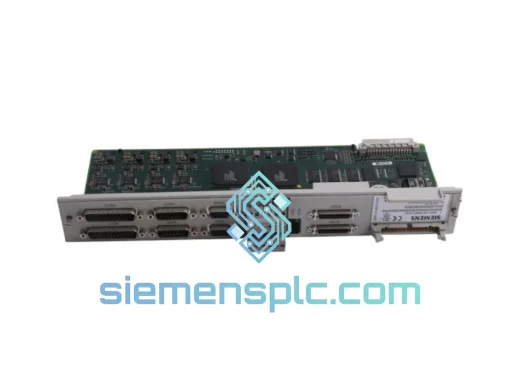
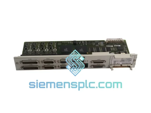
Siemens 6SN1118-0DK23-0AA2 Closed-Loop Control Card
SIMODRIVE
Origin DE
PLC / Drive Control Module
Siemens
RFQ Ready
Siemens 6SN1118-0DK23-0AA1 Digital Control Module
SIMODRIVE
Origin DE
PLC & Drive Control Module
Siemens
RFQ Ready
Siemens 6SL3210-1KE18-8UP1 AC Drive Power Module
SINAMICS
Origin DE
AC Drive Power Module