Siemens
In Stock OK
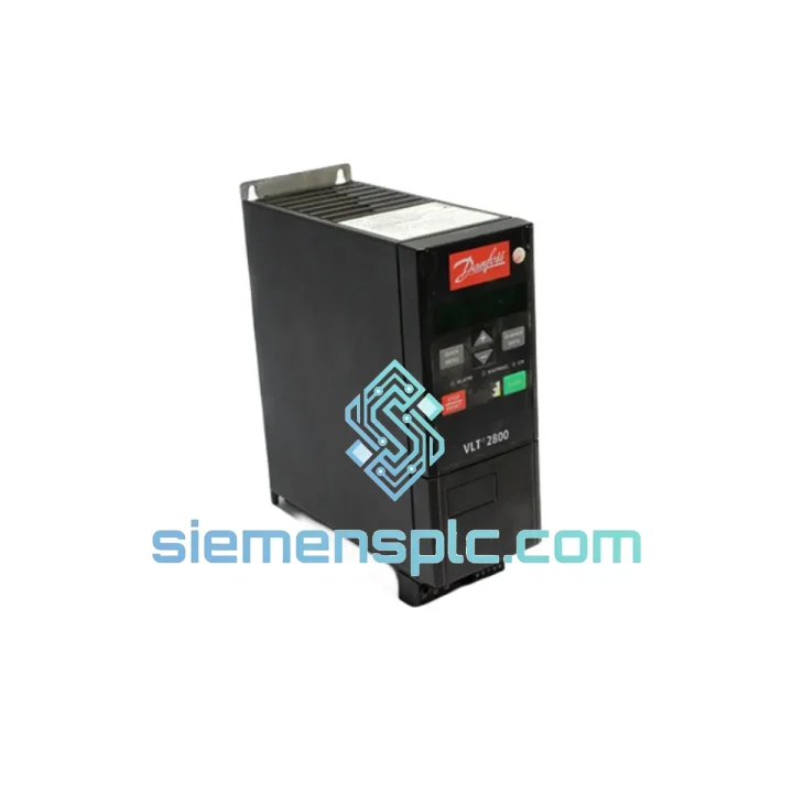
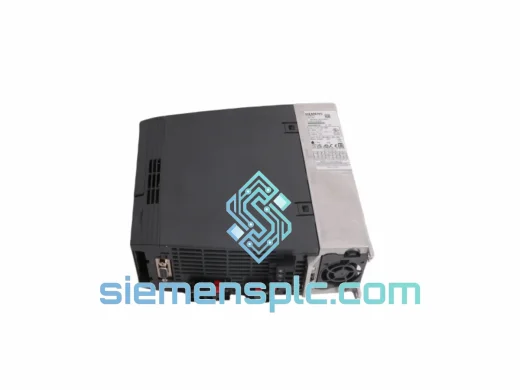
Siemens VLT2800 AC Variable Frequency Drive – VLT 2800 Series
Request verified availability, condition, replacement risk review, packing options and courier lead time for VLT2800.
BrandSiemens
Part NumberVLT2800
ConditionAvailability Check
Lead TimeRFQ Confirmation
DocumentsDatasheet / photos by RFQ
ShippingExport packing available
Auto-filled RFQ
VLT2800
Click Request Quote and the part number is inserted into the inquiry form automatically.
- Reply by email: [email protected]
- WhatsApp / Tel: +86 18359268345
- Mon-Sat 9:00-18:00 GMT+8
Procurement Data
Key Product Information
Core fields for model confirmation and RFQ routing. Detailed product narrative remains below.
- Brand
- Siemens
- Primary Part Number
- VLT2800
- Product Type
- AC Variable Frequency Drive
- Product Family
- Other series
- Country of Origin
- DE
- Catalog Category
- Motor Drives
- Humidity
- 5–95% RH, non-condensing
- Warranty
- 12 months from dispatch date
Model confirmed for inquiry
VLT2800
Send quantity, destination and urgency. The RFQ form keeps this part number attached.
Request Quote
Product Overview
Siemens VLT2800 AC Drive: Precision Motor Speed Regulation in Closed-Loop and Open-Loop Industrial Processes
The VLT2800 is a panel-mount AC variable frequency drive manufactured under the Siemens VLT 2800 series designation, covering a power range of 0.37 kW to 11 kW. Its primary function within an industrial control loop is to serve as the actuator between the supervisory PLC layer and the motor-load interface — accepting a speed or torque reference signal and translating it into a pulse-width-modulated three-phase output voltage with sub-millisecond update latency. The drive supports both V/f scalar control and open-loop flux vector control, selectable per application without hardware modification.
In pump and fan installations, the VLT2800 operates in a pressure or flow feedback loop where the PLC transmits a 4–20 mA setpoint derived from a field transmitter. The drive’s internal PID controller — configurable with independent proportional, integral, and derivative gain parameters — closes the loop locally, reducing PLC scan-cycle dependency and maintaining process stability even during communication interruptions. This distributed control architecture is particularly relevant in water treatment and HVAC applications where process continuity cannot tolerate PLC communication latency.
For conveyor and material handling applications, the drive’s programmable S-curve ramp function shapes the acceleration and deceleration profile to eliminate jerk forces at the mechanical coupling. The ramp time is independently configurable for acceleration and deceleration from 0.01 to 3,600 seconds, with a resolution that allows precise tuning to the inertia characteristics of the driven load without requiring external mechanical dampers.
The VLT2800’s DC bus architecture incorporates a pre-charge circuit that limits inrush current during power-up to below 10 A regardless of drive rating, protecting upstream fusing and contactors from repetitive thermal stress in applications with frequent power cycling. The DC bus voltage is continuously monitored; an overvoltage controller modulates the output frequency to absorb regenerative energy from decelerating loads before the bus voltage reaches the hardware trip threshold, extending the operational window without requiring an external braking resistor in low-inertia applications.
📩 Real-time Stock & RFQ: [email protected] | WhatsApp: +86 18359268345
Technical Parameters
| Parameter | Specification |
|---|---|
| Part Number | VLT2800 |
| Brand | Siemens |
| Product Series | VLT 2800 |
| Drive Type | AC Variable Frequency Drive (VFD) |
| Power Range | 0.37 kW – 11 kW |
| Input Supply (1-Phase) | 200–240 V AC ±10%, 50/60 Hz |
| Input Supply (3-Phase) | 200–240 V AC or 380–480 V AC ±10%, 50/60 Hz |
| Output Frequency | 0.2 – 1000 Hz |
| Output Voltage | 0 – 100% of rated input voltage |
| Control Modes | V/f scalar; Open-loop flux vector |
| PWM Carrier Frequency | 3 – 14 kHz (user-programmable) |
| Analog Inputs | 2 × configurable: 0–10 V DC or 4–20 mA |
| Digital Inputs | 5 × 24 V DC, programmable function |
| Relay Outputs | 2 × Form C relay, 240 V AC / 2 A |
| Analog Output | 1 × 0–20 mA, scalable to process variable |
| Serial Interface | RS-485; Modbus RTU / FC protocol |
| Fieldbus Options | Profibus DP, DeviceNet (via option card) |
| Enclosure Rating | IP20 standard; IP55 available (model-dependent) |
| Ambient Temperature | –10°C to +40°C; derated to +50°C |
| Storage Temperature | –25°C to +65°C |
| Humidity | 5–95% RH, non-condensing |
| Altitude | ≤1000 m without derating |
| EMC Standard | EN 61800-3, Category C2 |
| Certifications | CE, UL, cUL |
| Braking Method | Internal brake chopper; external resistor required for high-inertia loads |
| Motor Protection | ETR thermal model, phase loss, overcurrent, overvoltage, undervoltage, short-circuit |
| Warranty | 12 months from dispatch date |
Hardware Logical Analysis
The VLT2800 power stage is constructed around a six-pulse diode rectifier front end feeding a capacitor-filtered DC bus, followed by a three-phase IGBT inverter bridge. The IGBT gate drivers incorporate active desaturation detection circuits that monitor collector-emitter voltage during the on-state; a desaturation event — indicative of a shoot-through or output short-circuit condition — triggers a hardware-level gate shutdown within 2–3 µs, independent of the DSP control loop. This response time is two orders of magnitude faster than software-based overcurrent protection, preserving IGBT junction integrity under fault conditions that would destroy unprotected devices.
The DC bus capacitor bank is engineered with a capacitance-to-power ratio that sustains inverter operation through input voltage interruptions of up to 15 ms at rated load. This characteristic is derived from the stored energy equation E = ½CV², where the bus capacitance is selected to maintain bus voltage above the undervoltage trip threshold during the interruption interval. In grid environments with frequent voltage dips — common in industrial facilities with large motor starting events on shared feeders — this design prevents nuisance trips without requiring an external UPS or ride-through module.
EMC compliance is achieved through a layered suppression architecture. The integrated RFI filter (on applicable models) attenuates conducted emissions on the supply lines to EN 55011 Class B limits using a combination of common-mode chokes and X/Y capacitors. The drive’s internal PCB layout separates the control signal ground plane from the power stage ground plane with a defined isolation gap, reducing capacitive coupling of switching noise into the analog input circuitry. This separation is critical in installations where the VLT2800 shares a control cabinet with 4–20 mA transmitter wiring or thermocouple extension cables.
The open-loop flux vector algorithm executes a real-time motor model on the drive’s DSP, estimating rotor flux angle from measured stator current and terminal voltage without encoder feedback. The model parameters — stator resistance, leakage inductance, and magnetizing inductance — are identified automatically during the AMA (Automatic Motor Adaptation) routine, which applies a controlled test signal sequence to the motor at standstill and computes the equivalent circuit parameters from the measured response. This eliminates manual motor data entry and reduces commissioning time for standard IEC induction motors to under 10 minutes.
System Integration Benefits
- Local PID process control: The built-in PID controller accepts a process feedback signal directly at the drive’s analog input, enabling closed-loop pressure, flow, or temperature control without consuming PLC processing resources or network bandwidth for setpoint correction cycles.
- Flying start synchronization: The drive detects the rotational speed and direction of a coasting motor and synchronizes its output frequency before applying voltage, eliminating the mechanical shock and process interruption associated with conventional zero-speed restart sequences in fan and pump applications.
- Multi-speed preset operation: Up to eight discrete speed setpoints are stored in drive parameters and selectable via digital input combinations, enabling step-speed control in applications such as multi-stage conveyor indexing without requiring analog output wiring from the PLC.
- Fault event logging with operational context: The drive records the last 10 fault events with associated operating data — output frequency, output current, DC bus voltage, and thermal load percentage at the moment of fault — providing the diagnostic data required for root-cause analysis without external instrumentation.
- Sleep and wake function for energy management: In variable-torque applications, the drive monitors the process variable and halts motor operation when demand falls below a configurable threshold, restarting automatically when the wake condition is met. This function operates at the drive level, independent of PLC logic, reducing energy consumption during low-demand periods.
- Thermistor input for motor thermal protection: A dedicated thermistor input on the control terminal strip accepts a PTC or NTC motor thermistor signal, providing direct motor winding temperature monitoring and trip capability without an external thermistor relay module.
- Scalable communication architecture: The native RS-485 Modbus RTU port supports integration with Siemens S7-series, Mitsubishi MELSEC, and Omron NJ/NX PLCs using standard function blocks. Optional Profibus DP and DeviceNet cards extend compatibility to DCS architectures, providing a hardware-consistent upgrade path as system requirements evolve.
- Configurable relay output logic: Both relay outputs support programmable trigger conditions — including drive ready, motor running, fault active, current limit reached, and frequency threshold — enabling direct hardwired interlocking with upstream contactors, safety relays, and alarm annunciators without PLC intermediate logic.
Quality Assurance & Global Logistics
Units are sourced through verified OEM distribution channels with full batch-level traceability to Siemens manufacturing records. Each unit dispatched from our Xiamen, China facility undergoes a pre-shipment electrical verification protocol covering: DC bus capacitance measurement against factory tolerance bands, IGBT gate drive signal integrity check at 50 Hz output frequency, analog input calibration verification at 4 mA and 20 mA reference points, and Modbus RTU register read/write functional test. Units that fail any verification step are quarantined and excluded from inventory.
Export packaging conforms to IEC 60068-2-27 mechanical shock requirements: each unit is enclosed in an anti-static polyethylene bag with silica gel desiccant, seated in custom-profile EPE foam inserts within a double-wall corrugated carton. Gross weight and dimensional data are pre-declared for air freight acceptance. Each shipment is accompanied by a commercial invoice with accurate HS code 8504.40 classification, packing list, and certificate of conformity for customs clearance in EU, US, UK, and Southeast Asian jurisdictions.
Logistics options from Xiamen include DHL Express (3–5 business days to major destinations), FedEx International Priority, UPS Worldwide Expedited, and sea freight LCL consolidation for volume orders. Export documentation — including ECCN classification statements and end-user declarations where required — is prepared in-house by personnel with direct experience in industrial automation equipment export compliance.
A 12-month warranty from the dispatch date covers manufacturing defects and component failure under rated operating conditions. Warranty service follows a replacement-first protocol: a replacement unit is dispatched upon confirmation of the return shipment tracking number, minimizing production downtime for the end user.
Contact Information
📧 Email: [email protected]
📱 WhatsApp: +86 18359268345
🌐 Web: siemensplc.com
📍 Location: Xiamen, China
© 2026 siemensplc.com. All rights reserved.
Ready to quote
[email protected]
Send This Part Number to Sales
RFQ workflow
Quality workflow ->
Confirmation Process
01Model confirmation
We check the full part number, brand, series and visible nameplate information before quotation.
02Availability reply
Sales confirms stock path, condition option, quantity and realistic lead time for export dispatch.
03Packing & courier
DHL, FedEx, UPS or buyer courier arrangements can be reviewed with packing requirements.
Continue sourcing
Browse full catalog ->
Related Automation Parts
Similar brand or category products for fast comparison and multi-item RFQ lists.
Siemens
RFQ Ready
Siemens 6SN1118-0DK23-0AA2 Closed-Loop Control Card
SIMODRIVE
Origin DE
PLC / Drive Control Module
Siemens
RFQ Ready
Siemens 6SN1118-0DK23-0AA1 Digital Control Module
SIMODRIVE
Origin DE
PLC & Drive Control Module
Siemens
RFQ Ready
Siemens 6SL3210-1KE18-8UP1 AC Drive Power Module
SINAMICS
Origin DE
AC Drive Power Module