SYSTEM
RFQ Ready
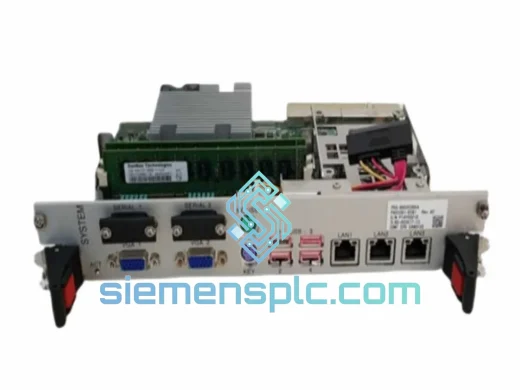
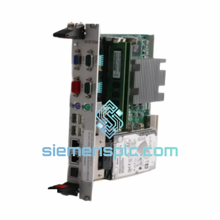
SYSTEM PDS-BX02E0954 PA03381-B393 Servo Control Card
Origin Not specified
Servo Control Card
Request verified availability, condition, replacement risk review, packing options and courier lead time for PDS-BX02S1421.
Click Request Quote and the part number is inserted into the inquiry form automatically.
Core fields for model confirmation and RFQ routing. Detailed product narrative remains below.
The SYSTEM PDS-BX02S1421 PA03381-B399 is a dedicated servo control card engineered for closed-loop axis management within SYSTEM-platform servo drive architectures. Its function is not peripheral — it sits at the intersection of the host controller’s trajectory commands and the power stage’s current regulation loop, translating interpolated position references into real-time torque demand signals with deterministic latency. In multi-axis configurations, this card governs the timing relationship between command receipt and PWM output update, a parameter that directly determines contouring accuracy in coordinated motion profiles.
Unlike generic motion interface boards, the PDS-BX02S1421 is designed around the SYSTEM proprietary backplane bus protocol, which uses a synchronous, time-slotted communication frame to eliminate arbitration jitter between the CPU module and each axis card. This architecture ensures that position loop closure occurs at a fixed, predictable interval regardless of the number of active axes on the rack — a property essential for applications where axis-to-axis phase error must remain below 10 µs.
The card accepts incremental encoder feedback with quadrature decoding and supports resolver-to-digital conversion through an onboard R/D converter stage, allowing it to interface with both optical encoder and resolver-equipped servo motors without external signal conditioning hardware. The feedback path includes hardware-level signal integrity monitoring: loss of encoder signal or excessive noise on the differential pair triggers a fault latch within one servo cycle, preventing uncontrolled axis runaway before the host CPU can respond through software.
From a system integration standpoint, the PDS-BX02S1421 PA03381-B399 is a drop-in replacement for failed or degraded units within existing SYSTEM servo drive racks. The card’s connector pinout, backplane slot assignment, and parameter memory structure are fully compatible with the original OEM specification, meaning no axis re-tuning or parameter re-entry is required after substitution — a critical factor in minimizing unplanned downtime in production environments where re-commissioning time is measured in lost throughput rather than engineering hours.
Real-time Stock & RFQ: [email protected] | WhatsApp: +86 18359268345
| Parameter | Specification |
|---|---|
| Manufacturer | SYSTEM |
| Part Number | PDS-BX02S1421 PA03381-B399 |
| Module Category | Servo Drive Control Card |
| Form Factor | Plug-in PCB card, backplane-mounted |
| Backplane Interface | SYSTEM proprietary synchronous bus |
| Feedback Input Types | Incremental encoder (A/B/Z differential), Resolver (via onboard R/D converter) |
| Encoder Input Frequency | Up to 4 MHz quadrature (model-dependent) |
| Position Loop Update Rate | Synchronous with backplane frame cycle (typically 125 µs – 500 µs) |
| Command Interface | Torque/velocity reference via backplane; position reference from host CPU trajectory generator |
| Fault Detection | Encoder loss, overcurrent, overvoltage, communication timeout, thermal warning |
| Operating Temperature | 0 °C to +55 °C |
| Storage Temperature | -25 °C to +70 °C |
| Relative Humidity | 5% to 95% RH, non-condensing |
| EMC Compliance | CE (EMC Directive 2014/30/EU) |
| RoHS Status | Compliant |
| Weight | Approx. 100 g |
| Condition | Genuine original / tested surplus |
| Warranty | 12 months replacement warranty |
The PDS-BX02S1421 PA03381-B399 implements a two-stage signal chain between the feedback transducer and the backplane data bus. In the first stage, the onboard ASIC performs quadrature decoding and position counter accumulation at hardware speed, entirely independent of the card’s local microcontroller. This separation ensures that encoder pulses are never lost due to firmware interrupt latency — a failure mode common in software-decoded feedback implementations that causes cumulative position error under high-speed axis motion.
The second stage involves the local DSP core, which executes the position and velocity estimation filter, applies configurable notch filtering to suppress mechanical resonance frequencies in the 50–500 Hz range, and formats the processed feedback data for transmission across the backplane bus in the next synchronous frame slot. The DSP operates from a dedicated clock domain isolated from the backplane interface logic, preventing bus activity from introducing jitter into the control computation cycle.
EMC design on this card follows a multi-layer PCB strategy with dedicated ground planes separating the analog feedback input section from the digital processing section. The encoder input lines are routed through common-mode chokes and TVS diode arrays before reaching the decoder ASIC, providing protection against conducted interference from servo motor cable capacitive coupling — a known source of false encoder counts in long-cable installations. The backplane connector uses a controlled-impedance differential pair layout to maintain signal integrity at the bus operating frequency without requiring external termination components.
The fault latch architecture is implemented in hardware logic rather than firmware, meaning that critical faults — encoder loss, overcurrent detection — assert the drive inhibit signal within one clock cycle of fault detection, independent of the DSP execution state. This hardware-first fault response eliminates the risk of a firmware hang condition masking a safety-critical fault during axis operation.
Every SYSTEM PDS-BX02S1421 PA03381-B399 unit dispatched from our Xiamen, China facility is sourced directly from authorized distribution channels or verified surplus stock with full traceability documentation. Prior to shipment, each card undergoes visual inspection of PCB, connector contacts, and component integrity against OEM reference standards, followed by a powered initialization test to confirm correct backplane communication response and absence of latent fault codes.
Units are packaged in anti-static ESD bags with foam cushioning inside double-wall corrugated cartons, conforming to ISTA 2A transit testing standards for electronic components. For international shipments, we prepare complete commercial invoice, packing list, and HS code documentation to facilitate customs clearance in major import markets including the EU, USA, Southeast Asia, and the Middle East. Standard dispatch lead time for in-stock units is 1–3 business days from order confirmation. Express air freight via DHL, FedEx, or UPS is available for urgent requirements, with typical transit times of 3–5 business days to most destinations. All shipments include tracking numbers and are covered by transit insurance.
The 12-month replacement warranty covers verified manufacturing defects and latent failures under normal operating conditions. Warranty claims are processed with a replacement-first policy — a tested replacement unit is dispatched before the failed unit is returned, minimizing production downtime for customers with urgent operational requirements.
Email: [email protected]
WhatsApp: +86 18359268345
Web: siemensplc.com
Location: Xiamen, China
© 2026 siemensplc.com. All rights reserved.
We check the full part number, brand, series and visible nameplate information before quotation.
Sales confirms stock path, condition option, quantity and realistic lead time for export dispatch.
DHL, FedEx, UPS or buyer courier arrangements can be reviewed with packing requirements.
Similar brand or category products for fast comparison and multi-item RFQ lists.