Woodward
In Stock OK
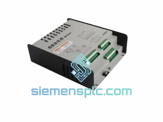
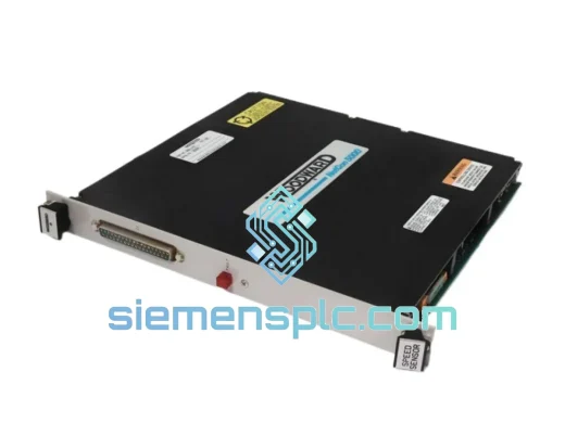
Woodward 9905-463 Speed Control Module – EG3P Series
Request verified availability, condition, replacement risk review, packing options and courier lead time for 9905-463.
BrandWoodward
Part Number9905-463
ConditionAvailability Check
Lead TimeRFQ Confirmation
DocumentsDatasheet / photos by RFQ
ShippingExport packing available
Auto-filled RFQ
9905-463
Click Request Quote and the part number is inserted into the inquiry form automatically.
- Reply by email: [email protected]
- WhatsApp / Tel: +86 18359268345
- Mon-Sat 9:00-18:00 GMT+8
Procurement Data
Key Product Information
Core fields for model confirmation and RFQ routing. Detailed product narrative remains below.
- Brand
- Woodward
- Primary Part Number
- 9905-463
- Product Type
- Speed Control Module
- Product Family
- Other series
- Manufacturer
- Woodward, Inc. (Fort Collins, Colorado, USA)
- Country of Origin
- US
- Catalog Category
- Motor Drives
- Operating Temp.
- -40°C to +70°C (IEC 60068-2-1/2 compliant)
- Warranty
- 12 months from dispatch date, covering defects in materials and workmanship
Model confirmed for inquiry
9905-463
Send quantity, destination and urgency. The RFQ form keeps this part number attached.
Request Quote
Product Overview
Woodward 9905-463 EG3P Speed Control Module – Governor Drive Unit: Procurement and Control-Loop Architecture Analysis
The Woodward 9905-463 is a dedicated isochronous/droop speed control module belonging to the EG3P governor product family. It occupies the signal-processing and actuator-drive tier of a turbine or reciprocating-engine governor loop — sitting between the magnetic pickup (MPU) speed sensor and the electrohydraulic or electromechanical actuator. Its function is deterministic: convert a frequency-domain speed signal into a calibrated proportional current output that positions the fuel control actuator with sub-100 ms closed-loop correction authority.
In power generation, oil and gas compression, and marine propulsion contexts, the 9905-463 is not a commodity item. It is a precision analog control instrument whose internal gain, droop, and stability trim settings are calibrated to a specific engine-actuator pairing. Substituting an uncalibrated or counterfeit board into a live governor loop introduces speed instability, hunting, and — in worst-case load-rejection events — overspeed trip conditions. Procurement teams sourcing this module must treat it with the same rigor applied to safety-instrumented system (SIS) components.
Real-time Stock & RFQ: [email protected] | WhatsApp: +86 18359268345
Technical Parameters
| Part Number | 9905-463 |
| Manufacturer | Woodward, Inc. (Fort Collins, Colorado, USA) |
| Product Family | EG3P Speed Control Series |
| Control Modes | Isochronous (0% droop) / Adjustable Droop (0–10%) |
| Supply Voltage | 18–40 VDC (nominal 24 VDC) |
| Quiescent Current Draw | ≤ 250 mA @ 24 VDC (no-load actuator output) |
| Speed Sensor Input | Magnetic Pickup Unit (MPU), 2-wire passive, 100–10,000 Hz |
| MPU Signal Amplitude | 1.0 Vrms minimum at lowest governed speed |
| Actuator Output | Proportional DC current, compatible with EG3P and equivalent electrohydraulic actuators |
| Speed Reference Input | Internal potentiometer or external 0–5 VDC analog reference |
| Governor Response Time | < 100 ms from speed deviation detection to actuator correction initiation |
| Droop Adjustment Range | 0–10%, front-panel trimmer, ±0.5% resolution |
| Gain Adjustment | Proportional (P) and Integral (I) trim potentiometers, accessible without module removal |
| Operating Temperature | -40°C to +70°C (IEC 60068-2-1/2 compliant) |
| Storage Temperature | -55°C to +85°C |
| Relative Humidity | 5–95% non-condensing |
| Enclosure / Mounting | DIN-rail (TS35 / EN 60715), IP20 |
| Dimensions | Approx. 160 × 100 × 45 mm (L × W × H) |
| Weight | Approx. 450 g |
| Certifications | CE (EMC Directive 2014/30/EU), UL Listed (original production batch) |
| Reference Manual | Woodward Manual 82510 (EG3P Speed Control) |
| HS Code | 8537.10 (Boards, panels, consoles for electric control) |
| Lead Time | In-stock units: ships within 2 business days of payment. Pre-order: 7–15 business days subject to sourcing verification. |
| Warranty | 12 months from dispatch date, covering defects in materials and workmanship |
Hardware Logical Analysis
The 9905-463 implements a classical proportional-integral (PI) governor algorithm in analog hardware — not firmware. This architectural choice has direct implications for reliability and maintainability in field environments where firmware corruption, memory wear, and communication bus faults are failure vectors for digital controllers.
Speed Signal Conditioning Chain: The MPU input stage uses a passive bandpass filter tuned to the 100–10,000 Hz operating range, followed by a zero-crossing frequency-to-voltage (F/V) converter. The F/V stage produces a DC voltage linearly proportional to engine speed, with a conversion gain that can be trimmed to match different flywheel tooth counts without external signal conditioning hardware. This eliminates the need for a separate speed signal conditioner in retrofit applications where the original tooth count differs from the standard EG3P configuration.
PI Control Loop Architecture: The error amplifier computes the difference between the F/V output (actual speed) and the speed reference setpoint. The proportional path applies a gain-trimmed amplification directly to the error signal. The integral path charges a film capacitor at a rate proportional to the error magnitude — the I-term trim potentiometer adjusts the RC time constant of this integrator. The summed P+I output drives the actuator current amplifier. Because both gain paths are implemented in discrete analog circuitry, the control loop executes continuously with no scan-cycle latency — a property that digital PLCs with 10–50 ms scan times cannot replicate in high-speed governor applications.
EMC Design: The module’s PCB layout separates the high-frequency MPU input traces from the DC actuator output traces using a ground plane partition. The actuator output stage uses a low-side current sink topology with a flyback diode rated for inductive actuator coil energy dissipation, protecting the output transistor from voltage spikes generated during rapid actuator de-energization. Input power filtering includes a common-mode choke and X/Y capacitors, providing attenuation of conducted emissions per EN 55011 Class A limits — relevant for installations in generator rooms with significant switching noise from adjacent variable-frequency drives or SCR rectifiers.
Droop Implementation: The droop circuit feeds a fraction of the actuator output current signal back to the speed reference summing junction, creating a negative feedback path that causes the governed speed setpoint to decrease as actuator output (and therefore engine load) increases. The droop percentage is set by a resistor divider whose ratio is adjusted via the front-panel droop trimmer. This hardware implementation ensures droop behavior is maintained even during power supply transients that might reset a microcontroller-based governor’s droop register.
Thermal Stability: Critical resistors in the F/V converter and error amplifier are specified at ±25 ppm/°C temperature coefficient — a tolerance class that maintains speed regulation accuracy within ±0.25% across the full -40°C to +70°C operating range without field recalibration. This is particularly relevant for outdoor generator installations in desert climates (ambient up to +55°C with panel heating) and arctic environments (cold-start at -40°C).
System Integration Benefits
- Zero scan-cycle latency: Analog PI execution is continuous — no discrete time steps. Speed corrections initiate within microseconds of deviation detection, compared to 10–50 ms for PLC-based soft governors. This matters in load-rejection events where overspeed develops at rates of 50–200 RPM/second.
- Direct MPU compatibility without signal conditioning: The onboard F/V converter accepts raw MPU signals from 1.0 Vrms minimum, eliminating the signal conditioner module that competing digital governors require. This reduces panel BOM by one component and removes a failure point from the signal chain.
- Isochronous parallel operation: In multi-generator bus systems, the 9905-463 supports isochronous load sharing when paired with a Woodward 2301A/2301D load-sharing module. The droop circuit’s analog summing junction accepts the load-sharing bias signal directly, with no protocol conversion or communication latency between units.
- Actuator current loop diagnostics: The actuator output is a current-regulated loop. An open-circuit actuator wiring fault causes the output current to collapse to zero, which the governor interprets as a maximum fuel demand condition — a fail-safe behavior that drives the actuator to minimum fuel position (spring return) rather than maximum, preventing runaway in most actuator configurations.
- Field-adjustable stability without laptop: P and I trim potentiometers are accessible on the module face without removing the unit from the DIN rail. Stability adjustments during commissioning or after actuator replacement require only a small screwdriver — no programming terminal, no firmware upload, no communication protocol.
- Wide supply voltage tolerance: The 18–40 VDC input range accommodates both 24 VDC nominal systems and 32 VDC battery-backed systems common in marine and offshore applications, without a separate DC/DC converter or voltage regulator module.
- Deterministic behavior under power supply disturbance: Because the control algorithm is implemented in analog hardware with no volatile memory, the module resumes normal governor operation within the RC time constant of the integrator (typically < 500 ms) after a power supply dip or brownout — without the reboot sequence, initialization delay, or configuration reload that a microcontroller-based governor requires.
- Backward compatibility with legacy EG3P actuator inventory: The 9905-463 is electrically and mechanically interchangeable with earlier EG3P speed control boards in the same product family. Facilities with existing EG3P actuator infrastructure can replace a failed control module without actuator replacement, preserving capital investment in the mechanical governor hardware.
Quality Assurance & Global Logistics
Every Woodward 9905-463 dispatched from siemensplc.com undergoes a structured four-stage inspection protocol before release for shipment.
Stage 1 — Visual and Component Integrity Inspection: The PCB is examined under 10× magnification for solder joint integrity, component substitution, burned traces, corrosion on terminal blocks, and label authenticity. Woodward part number silk-screen, date codes, and revision markings are cross-referenced against documented authentic samples. Any unit with altered labels, non-original components, or evidence of prior repair is rejected.
Stage 2 — Powered Functional Verification: The module is energized at 24 VDC and a calibrated MPU signal simulator is applied at the speed input. Actuator output current linearity, droop switching response, and isochronous setpoint tracking are measured against Woodward factory specification tolerances. Test data is logged and available as a Test Report on request.
Stage 3 — Documentation Package Assembly: Each unit ships with a Certificate of Conformance (COC) stating part number, sourcing declaration, inspection sign-off, and 12-month warranty terms. Commercial Invoice, Packing List, Country of Origin (COO) Declaration, and HS Code 8537.10 classification are included as standard export documentation — covering customs clearance requirements for EU, US, Middle East, and Southeast Asian import regimes.
Stage 4 — ESD-Protected Packaging: Units are sealed in anti-static bags, placed in foam-lined inner boxes, and packed in double-wall corrugated outer cartons with silica gel desiccant. Gross weight and dimensions are declared on the Packing List. Pre-shipment photographs of the packed unit are available on request.
Logistics from Xiamen, China: Xiamen Gaoqi International Airport (XMN) and Xiamen Port provide direct access to DHL Express, FedEx International Priority, and UPS Worldwide services with transit times of 3–5 business days to Europe, 4–6 days to North America, and 2–3 days to Southeast Asia. Sea freight LCL and EXW/FOB Xiamen terms are available for bulk orders. Xiamen’s status as a designated Free Trade Zone port enables streamlined customs declaration and reduced clearance lead times for industrial equipment exports under HS Chapter 85.
Contact Information
Email: [email protected]
WhatsApp: +86 18359268345
Web: siemensplc.com
Location: Xiamen, China
© 2026 siemensplc.com. All rights reserved.
Ready to quote
[email protected]
Send This Part Number to Sales
RFQ workflow
Quality workflow ->
Confirmation Process
01Model confirmation
We check the full part number, brand, series and visible nameplate information before quotation.
02Availability reply
Sales confirms stock path, condition option, quantity and realistic lead time for export dispatch.
03Packing & courier
DHL, FedEx, UPS or buyer courier arrangements can be reviewed with packing requirements.
Continue sourcing
Browse full catalog ->
Related Automation Parts
Similar brand or category products for fast comparison and multi-item RFQ lists.
Woodward
RFQ Ready
WOODWARD SST-DN3-PCI-2 DeviceNet PCI Interface Card – SST Series
Origin US
PLC Communication Module