Yaskawa
In Stock OK
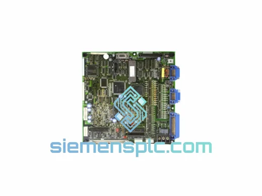
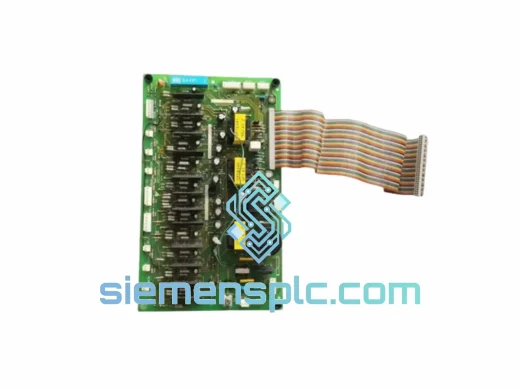
YASKAWA YPCT31240-1C Drive Control Board – Varispeed Series
Request verified availability, condition, replacement risk review, packing options and courier lead time for YPCT31240-1C.
BrandYaskawa
Part NumberYPCT31240-1C
ConditionAvailability Check
Lead TimeRFQ Confirmation
DocumentsDatasheet / photos by RFQ
ShippingExport packing available
Auto-filled RFQ
YPCT31240-1C
Click Request Quote and the part number is inserted into the inquiry form automatically.
- Reply by email: [email protected]
- WhatsApp / Tel: +86 18359268345
- Mon-Sat 9:00-18:00 GMT+8
Procurement Data
Key Product Information
Core fields for model confirmation and RFQ routing. Detailed product narrative remains below.
- Brand
- Yaskawa
- Primary Part Number
- YPCT31240-1C
- Product Type
- Drive Control Board
- Series / Family
- F7 Series
- Manufacturer
- YASKAWA Electric Corporation
- Country of Origin
- JP
- Catalog Category
- Motor Drives
- Operating Temp.
- -10°C to +50°C (derating above 40°C)
- Humidity
- 5% – 95% RH, non-condensing
- Warranty
- 12 months from date of shipment
Model confirmed for inquiry
YPCT31240-1C
Send quantity, destination and urgency. The RFQ form keeps this part number attached.
Request Quote
Product Overview
YASKAWA YPCT31240-1C Drive Control Board — Gate Signal Architecture and Control Loop Authority in Varispeed G7/F7 Series VFDs
The YPCT31240-1C is the primary control PCB assembly used in YASKAWA’s Varispeed G7 and F7 series variable frequency drives. Within the drive’s internal hierarchy, this board occupies the position directly above the gate driver stage: it receives speed and torque references from the operator interface or fieldbus, executes the vector control algorithm in real time, and outputs precisely timed PWM gate signals to the IGBT power module. Without a fully functional YPCT31240-1C, the drive cannot perform closed-loop flux vector control, cannot execute fault diagnostics, and cannot communicate with upstream SCADA or DCS systems. This is not a peripheral component — it is the computational and signal-routing core of the entire drive system.
YASKAWA’s Varispeed G7 platform was engineered for high-performance applications where torque linearity at low speed, fast dynamic response, and deterministic fault handling are non-negotiable. The YPCT31240-1C implements YASKAWA’s proprietary flux vector control algorithm, which achieves torque response times below 5 ms and maintains speed regulation accuracy within ±0.01% of rated speed under closed-loop encoder feedback. These figures are not achievable with a substitute or non-OEM board — the firmware embedded in the onboard DSP is calibrated to the specific power stage characteristics of the G7/F7 chassis, including IGBT switching dead-time compensation, DC bus voltage feed-forward, and motor parameter auto-tuning tables.
Real-time Stock & RFQ: [email protected] | WhatsApp: +86 18359268345
Technical Parameters
| Parameter | Specification |
|---|---|
| Part Number | YPCT31240-1C |
| Manufacturer | YASKAWA Electric Corporation |
| Component Classification | Drive Control Board (Main PCB Assembly) |
| Compatible Drive Series | Varispeed G7, F7 Series Variable Frequency Drives |
| Control Method | Closed-loop flux vector / open-loop V/f / sensorless vector |
| Speed Regulation Accuracy | ±0.01% (closed-loop encoder), ±0.2% (open-loop) |
| Torque Response Time | <5 ms (flux vector mode) |
| PWM Carrier Frequency Range | 2.0 kHz – 15.0 kHz (software selectable) |
| Analog Input Channels | 3 × multi-function analog inputs (0–10 V / 4–20 mA) |
| Digital I/O | 8 × multi-function digital inputs, 5 × multi-function digital outputs |
| Encoder Interface | Incremental encoder input (A/B/Z phase, open collector or line driver) |
| Communication Ports | RS-422/485 MEMOBUS/Modbus RTU (standard); optional PROFIBUS-DP, DeviceNet, EtherNet/IP via option card |
| Onboard Processor | Fixed-point DSP with dedicated vector control execution core |
| Protection Functions | Overcurrent (OC), overvoltage (OV), undervoltage (UV), overtemperature (OH), ground fault (GF), output phase loss (LF) |
| Operating Temperature | -10°C to +50°C (derating above 40°C) |
| Storage Temperature | -20°C to +60°C |
| Humidity | 5% – 95% RH, non-condensing |
| Vibration Resistance | 9.8 m/s² (1G), 10–20 Hz |
| PCB Coating | Conformal coating on signal-layer traces (moisture and contamination resistance) |
| Shipping Weight | Approx. 4.46 kg (packaged) |
| Origin | Japan |
| Warranty | 12 months from date of shipment |
Hardware Logical Analysis
The YPCT31240-1C is structured around three distinct functional zones on a single multilayer PCB: the DSP computation zone, the analog signal conditioning zone, and the gate signal output zone. Understanding the interaction between these zones explains why OEM board integrity is mandatory for reliable drive operation.
DSP Computation Zone: The onboard fixed-point DSP executes the flux vector control algorithm at a cycle time synchronized to the PWM carrier period — typically 66 µs at a 15 kHz carrier. Within each cycle, the DSP reads rotor flux angle from the encoder interface, computes d-axis and q-axis current references, applies PI regulation, and outputs updated duty-cycle values to the PWM generation logic. The DSP also manages the motor parameter database populated during auto-tuning: stator resistance, leakage inductance, rotor time constant, and no-load current. These parameters are stored in onboard non-volatile memory and are specific to the motor connected during commissioning. A board replacement requires re-execution of the auto-tuning sequence to restore optimal vector control accuracy.
Analog Signal Conditioning Zone: Three multi-function analog input channels pass through precision instrumentation amplifiers with differential input topology, providing common-mode rejection ratios exceeding 80 dB. This architecture suppresses ground-loop noise and capacitively coupled interference from adjacent power cabling — a critical requirement in panel environments where VFD output cables run parallel to signal wiring. The analog-to-digital conversion resolution is 12 bits, yielding a speed reference resolution of approximately 0.024% of full scale, sufficient for applications requiring sub-RPM positioning accuracy at low speed.
Gate Signal Output Zone: The YPCT31240-1C generates six-channel complementary PWM signals for the three-phase IGBT bridge. Dead-time insertion — the blanking interval between upper and lower switch transitions — is implemented in hardware logic on the board, not in software, ensuring that dead-time compensation remains consistent regardless of DSP load. The gate signal output stage uses optocoupler isolation between the control-voltage domain (5 V logic) and the gate driver interface, providing a minimum isolation voltage of 2,500 V RMS. This galvanic barrier protects the DSP and all connected signal wiring from transients generated during IGBT switching, which can reach dV/dt rates exceeding 5,000 V/µs in high-power drive stages.
EMC Design: The board incorporates a multi-layer ground plane strategy: digital ground, analog ground, and chassis ground are separated at the PCB level and joined at a single star point near the power connector. Ferrite beads are placed on all inter-zone signal traces crossing the analog-digital boundary. Decoupling capacitors are distributed at 100 nF per IC power pin across the DSP zone, with bulk 10 µF tantalum capacitors at the zone power entry points. This layout reduces conducted emissions on the control supply rail and prevents DSP clock harmonics from coupling into the analog measurement channels.
System Integration Benefits
- Deterministic Torque Control at Zero Speed: The flux vector algorithm maintains full rated torque output at 0 Hz output frequency, enabling applications such as crane hoist control and vertical conveyor positioning where static load holding without mechanical braking is required.
- Fieldbus Transparency: The MEMOBUS/Modbus RTU port exposes all drive parameters, fault history, and real-time process variables as addressable registers, allowing PLC or SCADA systems to perform non-intrusive monitoring without interrupting drive operation.
- Multi-Function I/O Configurability: Each of the 8 digital inputs and 5 digital outputs can be independently assigned from a library of over 60 function codes, enabling the board to adapt to application-specific interlock logic, external fault inputs, and multi-speed preset configurations without additional relay hardware.
- Fault Diagnostics with Timestamp Logging: The onboard non-volatile memory stores the last 4 fault events with associated drive state data (output frequency, output current, DC bus voltage, heatsink temperature) at the moment of fault. This data is retrievable via the operator keypad or fieldbus, reducing fault diagnosis time from hours to minutes.
- Auto-Tuning for Motor Parameter Identification: The board executes a stationary auto-tuning routine that measures stator resistance and leakage inductance without rotating the motor shaft, enabling commissioning in applications where the load cannot be decoupled during setup.
- Carrier Frequency Adjustment for Acoustic Noise Reduction: PWM carrier frequency is adjustable from 2 kHz to 15 kHz in software, allowing engineers to shift audible motor noise above the human hearing threshold in noise-sensitive environments such as HVAC plant rooms and food processing facilities.
- Slip Compensation for Open-Loop Accuracy: In V/f control mode, the board applies automatic slip compensation based on measured output current, maintaining motor speed within ±0.5% of setpoint without encoder feedback — adequate for pump and fan applications where encoder installation is impractical.
- Seamless Option Card Expansion: The board’s option card slot accepts YASKAWA’s full range of communication and I/O expansion cards (PROFIBUS-DP, DeviceNet, EtherNet/IP, additional analog I/O), allowing the drive to integrate into any plant network architecture without hardware modification to the main control board.
Quality Assurance & Global Logistics
Every YPCT31240-1C unit supplied by siemensplc.com is sourced through verified channels with full traceability to YASKAWA’s authorized distribution network. Before dispatch, each board undergoes a structured inspection protocol: visual examination of all solder joints under magnification, continuity verification of inter-zone signal paths, and functional power-on test confirming DSP initialization, communication port response, and analog input calibration within OEM tolerance bands. Units are packaged in anti-static (ESD) shielding bags, placed in foam-lined rigid cartons, and sealed with tamper-evident tape. A condition report is included with each shipment.
Logistics operations are managed from Xiamen, China — a major international freight hub with direct access to DHL, FedEx, UPS, and SF Express international express networks. Standard express delivery to Europe, North America, Southeast Asia, and the Middle East is achieved within 3–5 business days. For urgent downtime situations, same-day dispatch is available for orders confirmed before 14:00 CST. All shipments include full commercial invoice documentation, packing lists, and country-of-origin certificates to facilitate customs clearance in regulated markets. Import duty and VAT guidance is available upon request for specific destination countries.
The 12-month warranty covers manufacturing defects and functional failure under normal operating conditions. Warranty claims are processed within 5 business days of receipt of the returned unit, with replacement dispatch or credit note issued upon confirmation of defect.
Contact Information
Email: [email protected]
WhatsApp: +86 18359268345
Web: siemensplc.com
Location: Xiamen, China
© 2026 siemensplc.com. All rights reserved.
Ready to quote
[email protected]
Send This Part Number to Sales
RFQ workflow
Quality workflow ->
Confirmation Process
01Model confirmation
We check the full part number, brand, series and visible nameplate information before quotation.
02Availability reply
Sales confirms stock path, condition option, quantity and realistic lead time for export dispatch.
03Packing & courier
DHL, FedEx, UPS or buyer courier arrangements can be reviewed with packing requirements.
Continue sourcing
Browse full catalog ->
Related Automation Parts
Similar brand or category products for fast comparison and multi-item RFQ lists.
Yaskawa
RFQ Ready
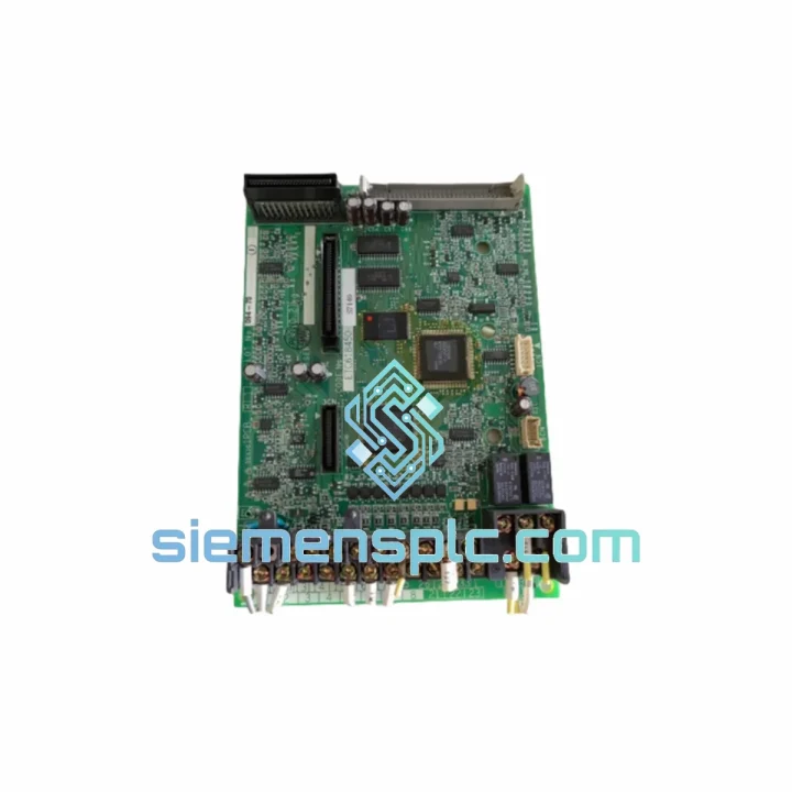
YASKAWA YPHT11017-1A Drive Control Board
Varispeed G7 F7 Series
Origin JP
PLC & Drive Control Board
Yaskawa
RFQ Ready
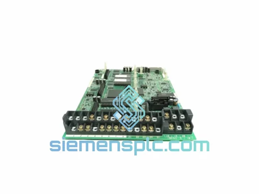
Yaskawa YPCT11077-1A VFD Control Board
YPCT Series Drive PCB
Origin JP
VFD Control Board
Yaskawa
RFQ Ready
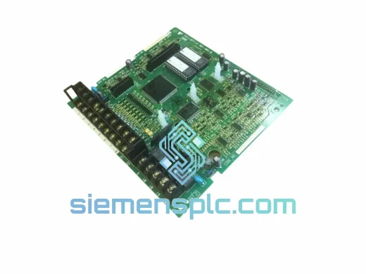
YASKAWA YPCT21092-1-4 Inverter Control Board
Industrial VFD
Origin JP
Inverter Control Board