Yokogawa
In Stock OK
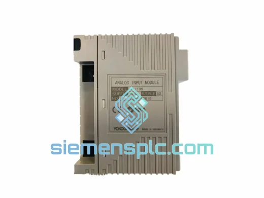
Yokogawa AAP135-S03 S2 Pulse Input Module – STARDOM FCN/FCJ
Request verified availability, condition, replacement risk review, packing options and courier lead time for AAP135-S03.
BrandYokogawa
Part NumberAAP135-S03
ConditionAvailability Check
Lead TimeRFQ Confirmation
DocumentsDatasheet / photos by RFQ
ShippingExport packing available
Auto-filled RFQ
AAP135-S03
Click Request Quote and the part number is inserted into the inquiry form automatically.
- Reply by email: [email protected]
- WhatsApp / Tel: +86 18359268345
- Mon-Sat 9:00-18:00 GMT+8
Procurement Data
Key Product Information
Core fields for model confirmation and RFQ routing. Detailed product narrative remains below.
- Brand
- Yokogawa
- Primary Part Number
- AAP135-S03
- Product Type
- Pulse Input Module
- Series / Family
- STARDOM
- Manufacturer
- Yokogawa Electric Corporation
- Country of Origin
- JP
- Catalog Category
- I/O Modules
- Operating Temp.
- 0 °C to +55 °C
- Warranty
- 12 months from date of shipment
Model confirmed for inquiry
AAP135-S03
Send quantity, destination and urgency. The RFQ form keeps this part number attached.
Request Quote
Product Overview
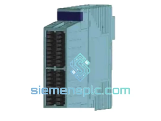
Yokogawa AAP135-S03 S2 — Pulse Input Module for STARDOM FCN/FCJ Distributed Control Architecture
The AAP135-S03 S2 is a four-channel pulse input module designed for slot-based installation within Yokogawa’s STARDOM FCN and FCJ autonomous controllers. Its primary function within a control loop is deterministic pulse accumulation and frequency measurement — translating raw field-device pulse trains from turbine meters, vortex flowmeters, positive-displacement meters, and encoder outputs into engineering-unit process values accessible to the FCN/FCJ CPU over the internal I/O bus. Unlike analog input modules that rely on 4–20 mA signal conditioning chains, the AAP135-S03 S2 accepts direct digital pulse signals, eliminating one conversion stage and the associated linearity error it introduces.
In flow-metering applications, the module operates as the primary totalizer front-end. Each channel maintains an independent 32-bit hardware counter clocked at up to 10 kHz for voltage-pulse inputs, accumulating counts without CPU intervention. The FCN firmware reads these counters on each scan cycle and applies the configured K-factor (pulses per unit volume) to derive instantaneous flow rate and accumulated total. This architecture ensures that no pulse is lost between scan cycles, a critical requirement in custody-transfer and fiscal metering installations where count integrity directly affects billing accuracy.
Real-time Stock & RFQ: [email protected] | WhatsApp: +86 18359268345
Technical Parameters
| Parameter | Specification |
|---|---|
| Part Number / SKU | AAP135-S03 S2 |
| Manufacturer | Yokogawa Electric Corporation |
| Series / Platform | STARDOM FCN / FCJ Autonomous Controller |
| Module Function | Pulse Input (Accumulation & Frequency Measurement) |
| Number of Input Channels | 4 (individually isolated) |
| Input Signal Types | Voltage pulse, dry contact closure, open-collector (NPN) |
| Max Input Frequency — Voltage Pulse | 10 kHz |
| Max Input Frequency — Contact Input | 100 Hz |
| Input Voltage Range (Voltage Pulse Mode) | 5 V DC to 30 V DC |
| Counter Register Width | 32-bit per channel (max count: 4,294,967,295) |
| Internal I/O Bus | STARDOM FCN/FCJ proprietary backplane bus |
| Power Consumption | ≤ 3.5 W (from base unit backplane) |
| Operating Temperature | 0 °C to +55 °C |
| Storage Temperature | −25 °C to +70 °C |
| Relative Humidity | 5 % to 95 % RH, non-condensing |
| Module Weight | 460 g |
| Mounting Method | Direct slot insertion into FCN/FCJ base unit |
| Certifications | CE (EMC + LVD), UL, cUL, RoHS |
| Country of Origin | Japan |
| Warranty | 12 months from date of shipment |
Hardware Logical Analysis
The AAP135-S03 S2 implements per-channel galvanic isolation using optocoupler barriers rated for at least 500 V DC isolation voltage between field wiring and the backplane logic domain. This design choice directly addresses the ground-potential differences that arise in large industrial installations where field instruments, junction boxes, and control panels share separate earthing networks. Without channel isolation, a ground loop between two meters at different potential would inject a common-mode current into the counter input, producing spurious counts or saturating the input comparator. The optocoupler barrier converts the field-side current pulse into a light pulse, which is then detected by a photodiode on the logic side — breaking the galvanic path entirely.
On the logic side, each channel feeds a dedicated hardware counter register rather than relying on CPU interrupt service routines. This is architecturally significant: interrupt-driven pulse counting on a shared CPU is subject to latency jitter caused by competing interrupt sources (Ethernet, serial, watchdog timers). At 10 kHz input frequency, a 50 µs interrupt latency window is sufficient to miss one pulse per cycle under worst-case CPU loading. The AAP135-S03 S2 eliminates this failure mode by decoupling the counting function from the CPU entirely — the 32-bit counter increments in hardware on every valid pulse edge, and the CPU reads the accumulated value at its own scan rate without risk of count loss.
The module’s input comparator threshold is designed to reject slow-rising signals and contact bounce. For voltage-pulse mode, the hysteresis band between the low-to-high and high-to-low switching thresholds prevents multiple counts from a single mechanical contact closure event. For contact-closure mode, the 100 Hz maximum frequency specification reflects the debounce filter time constant built into the input conditioning circuit — a deliberate hardware constraint that trades high-frequency capability for immunity to contact chatter in relay and limit-switch applications.
EMC performance is reinforced by the module’s physical construction: the PCB employs a ground-plane layer between the field-side and logic-side circuits, and the module housing provides shielding continuity to the FCN/FCJ chassis ground. This layered approach — optocoupler isolation, ground-plane separation, and chassis shielding — allows the module to operate within IEC 61000-4-4 (electrical fast transient) and IEC 61000-4-5 (surge) test levels without auxiliary external protection devices in most standard industrial environments.
System Integration Benefits
- Zero-loss pulse accumulation at 10 kHz: Hardware counter architecture guarantees no pulse is dropped between FCN scan cycles, preserving totalizer accuracy in high-throughput flow metering applications.
- Multi-signal-type compatibility: A single module accepts voltage pulse, dry contact, and open-collector inputs across its four channels simultaneously, eliminating the need for external signal converters or separate module types for mixed field-device installations.
- Deterministic scan-cycle data delivery: Counter values are latched and transferred to the FCN CPU on every deterministic scan cycle, ensuring that flow totals and frequency values are time-stamped consistently with other process variables in the same scan.
- 32-bit counter depth for unattended operation: At 10 kHz continuous input, the 32-bit counter reaches rollover after approximately 119.3 hours. The FCN firmware’s rollover-detection logic handles counter wrap-around transparently, enabling continuous unattended operation without manual counter reset.
- Per-channel isolation for multi-meter installations: Independent galvanic isolation on each channel allows connection to meters at different ground potentials within the same module, reducing wiring complexity and eliminating the need for isolating signal conditioners in multi-meter panels.
- Plug-and-play slot recognition: The STARDOM engineering tool automatically identifies the AAP135-S03 S2 upon slot insertion and populates the I/O tag database with the correct channel count, data types, and engineering-unit scaling parameters — reducing commissioning time compared to manually configured third-party I/O.
- Dual operating modes per channel: Each channel is independently configurable for accumulation (totalizer) mode or frequency measurement (Hz) mode via the FCN function block library, allowing a single module to serve both flow totalization and rotational speed monitoring within the same base unit.
- Compact slot footprint for space-constrained RTUs: The module occupies a single FCN/FCJ slot, preserving adjacent slots for analog or digital I/O expansion in remote terminal unit enclosures where DIN-rail space is limited.
Quality Assurance & Global Logistics
Every AAP135-S03 S2 unit dispatched from our Xiamen, China facility undergoes a structured pre-shipment verification process. Physical inspection confirms label authenticity, connector pin integrity, and the absence of mechanical damage consistent with counterfeit or refurbished units. Part numbers and revision codes are cross-referenced against Yokogawa’s official product database prior to listing and again at the point of order fulfillment.
Units are packed in anti-static bags with desiccant sachets, placed in foam-lined cartons rated for international air freight handling. For time-critical project requirements, DHL Express and FedEx International Priority services from Xiamen Gaoqi International Airport typically achieve 3–5 business day delivery to major industrial hubs in Europe, North America, Southeast Asia, and the Middle East. Sea freight consolidation is available for volume orders where lead time permits.
Export documentation — commercial invoice, packing list, certificate of origin, and HS Code 8537.10 classification — is prepared for every international shipment. For projects requiring CNAS-accredited inspection reports or third-party testing certificates, these can be arranged upon request prior to dispatch. All units carry a 12-month warranty from the date of shipment, covering manufacturing defects and functional failure under normal operating conditions.
Contact Information
Email: [email protected]
WhatsApp: +86 18359268345
Web: siemensplc.com
Location: Xiamen, China
© 2026 siemensplc.com. All rights reserved.
Ready to quote
[email protected]
Send This Part Number to Sales
RFQ workflow
Quality workflow ->
Confirmation Process
01Model confirmation
We check the full part number, brand, series and visible nameplate information before quotation.
02Availability reply
Sales confirms stock path, condition option, quantity and realistic lead time for export dispatch.
03Packing & courier
DHL, FedEx, UPS or buyer courier arrangements can be reviewed with packing requirements.
Continue sourcing
Browse full catalog ->
Related Automation Parts
Similar brand or category products for fast comparison and multi-item RFQ lists.
Yokogawa
RFQ Ready
Yokogawa NFBU200-S16 S1 DCS Backplane Base Unit – STARDOM FCN
STARDOM
Origin JP
DCS Backplane Base Unit
Yokogawa
RFQ Ready
Yokogawa NFAI135-S51-S2 Analog Input Module
STARDOM
Origin JP
Analog Input Module