Yokogawa
RFQ Ready
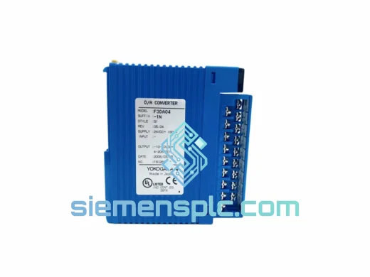
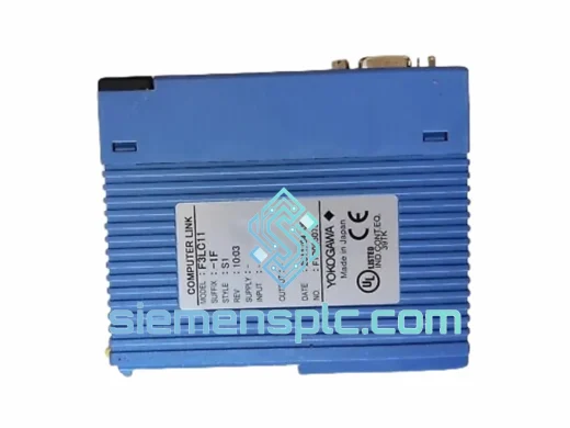
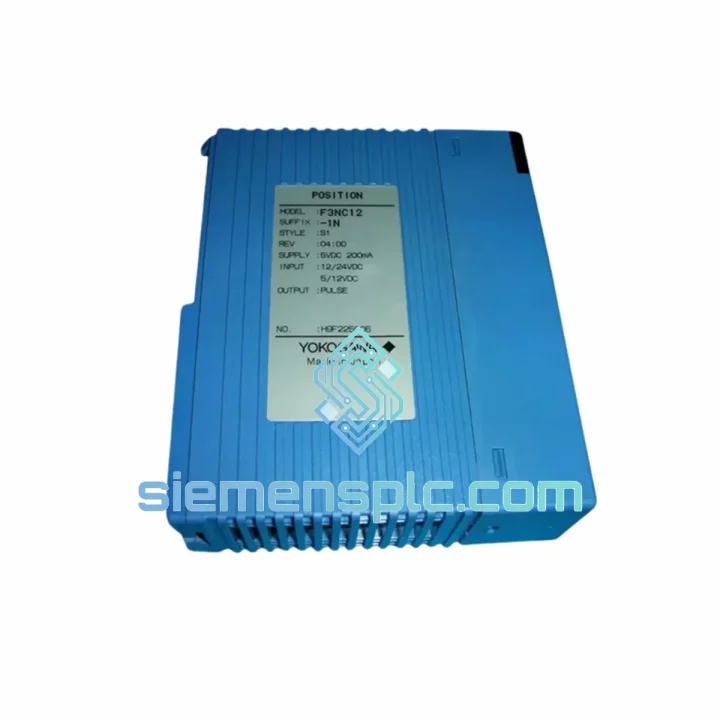
YOKOGAWA F3NC1Z-ON-Z01 Position Module – FA-M3 Series
FA-M3
Origin JP
Position Control Module
Request verified availability, condition, replacement risk review, packing options and courier lead time for F3NC12-1N.
Click Request Quote and the part number is inserted into the inquiry form automatically.
Core fields for model confirmation and RFQ routing. Detailed product narrative remains below.
The F3NC12-1N is a dedicated single-axis position control module engineered for YOKOGAWA’s FA-M3 Wide Series modular PLC architecture. Its core function within a motion control loop is to assume full responsibility for pulse-train generation and axis trajectory execution, offloading these tasks entirely from the FA-M3 CPU module. The module houses an onboard motion control ASIC that independently manages acceleration ramps, constant-velocity phases, deceleration profiles, and home-return sequences — all clocked from a local oscillator rather than the CPU’s task scheduler. This hardware separation is the architectural basis for the module’s deterministic output behavior: pulse frequency accuracy and profile fidelity are maintained regardless of CPU scan load, program size, or I/O service overhead.
In practical terms, the F3NC12-1N accepts positioning parameters — target position in pulses, command velocity in pulses per second, acceleration time constant in milliseconds — written by the CPU into a dual-port shared memory block on the module via the FA-M3 backplane bus. Once a start command is issued through the NC_MOVE or equivalent function block, the motion ASIC reads these parameters and executes the move autonomously. The CPU is released immediately to continue processing other ladder rungs, analog I/O, and communication tasks. The module reports axis status — in-position, alarm code, current command position, active input states — back to the CPU through the same shared register map, readable within one CPU scan cycle. This handoff model is what allows multi-axis FA-M3 systems to achieve coordinated motion across several F3NC12-1N modules without CPU throughput becoming a bottleneck.
The output stage drives a servo drive or stepper driver via open-collector NPN transistor outputs, supporting both CW/CCW dual-pulse mode and Pulse+Direction single-pulse mode. Maximum output frequency is 500 kpps (500,000 pulses per second), which at a typical servo drive electronic gear ratio of 1:1 corresponds to a command resolution of 500,000 encoder counts per second — sufficient for high-speed positioning in semiconductor handling, precision dispensing, and high-throughput assembly automation. The module occupies a single FA-M3 slot and draws 0.5 A at 5 VDC from the backplane power bus, making it compatible with standard FA-M3 power supply modules without derating calculations in typical multi-module configurations.
Real-time Stock & RFQ: [email protected] | WhatsApp: +86 18359268345
| Parameter | Specification |
|---|---|
| Model Number | F3NC12-1N |
| Manufacturer | YOKOGAWA Electric Corporation |
| Platform Series | FA-M3 Wide Series |
| Controlled Axes | 1 (independent) |
| Output Signal Type | Open-collector NPN transistor pulse train |
| Output Pulse Modes | CW/CCW dual-pulse; Pulse + Direction |
| Maximum Output Frequency | 500 kpps (500,000 pulses/sec) |
| Speed Setting Range | 1 pps – 500,000 pps |
| Position Data Range | −2,147,483,648 to +2,147,483,647 pulses (32-bit signed) |
| Positioning Modes | Absolute, Incremental |
| Control Modes | Position control, Speed control, Home return (DOG method) |
| Velocity Profile | Trapezoidal; configurable acceleration/deceleration time |
| Hardware Latch Input | 1 × LATCH input; sub-microsecond capture latency (ASIC-level) |
| External Inputs | Near-home (DOG), Forward limit (FLS), Reverse limit (RLS), Stop (STOP), Latch (LATCH) |
| Backplane Interface | FA-M3 internal parallel bus, 5 VDC logic |
| Power Consumption | 5 VDC, 0.5 A (backplane-supplied) |
| Operating Temperature | 0 °C to +55 °C |
| Storage Temperature | −20 °C to +70 °C |
| Relative Humidity | 10 % to 90 % RH, non-condensing |
| Vibration Resistance | IEC 60068-2-6: 10–57 Hz / 0.075 mm; 57–150 Hz / 9.8 m/s² |
| Shock Resistance | IEC 60068-2-27: 147 m/s², 11 ms half-sine, 3 axes |
| Module Weight | 360 g |
| Slot Occupancy | 1 × FA-M3 slot |
| Certifications | CE (EMC Directive + LVD), UL 508, cUL, RoHS compliant |
| Warranty | 12 months from date of shipment |
Motion ASIC and Dual-Port Shared Memory Interface. The F3NC12-1N’s motion control ASIC is the functional core of the module. It maintains an internal position counter, a velocity accumulator, and a profile state machine that transitions between acceleration, constant-velocity, and deceleration phases based on the configured ramp parameters. The ASIC’s clock source is independent of the FA-M3 CPU bus clock, which means pulse output timing is not subject to bus arbitration delays or CPU interrupt latency. The dual-port shared memory block — accessible simultaneously by the ASIC and the FA-M3 CPU — serves as the communication interface. The CPU writes command registers (target position, velocity, start/stop commands) and reads status registers (current position, speed, alarm word, input states) through this memory map. Access from the CPU side is synchronous with the FA-M3 backplane bus cycle, ensuring register reads and writes complete within a deterministic number of bus clock cycles.
Output Stage EMC Architecture. Each pulse output line is driven by an NPN open-collector transistor with a collector-emitter voltage rating compatible with 5–24 VDC servo drive input circuits. Transient voltage suppression (TVS) diodes are placed at the output connector to clamp inductive transients generated by long cable capacitance and drive input circuitry. The PCB layout separates the high-frequency pulse output section from the backplane logic section using a ground-plane partition, reducing capacitive coupling of switching noise into the backplane bus. The module’s metal housing is bonded to the FA-M3 rack ground rail, providing a low-impedance return path for shield currents and satisfying IEC 61000-4-4 (EFT/Burst, 2 kV) and IEC 61000-4-5 (Surge, 1 kV) immunity requirements without external filtering components.
Hardware Position Latch Mechanism. The LATCH input is connected directly to the ASIC’s interrupt capture logic, not to a firmware polling routine. On the rising edge of the LATCH signal, the ASIC captures the current value of the internal pulse counter into a dedicated latch register within one ASIC clock cycle — a latency measured in tens of nanoseconds rather than the microseconds typical of software interrupt service routines. This captured value is then available in the shared memory map for the CPU to read at the next scan. The mechanism is essential for applications such as flying-shear length control, registration mark detection in web printing, and encoder index synchronization, where the position at an external event must be recorded with accuracy that software polling cannot guarantee.
DOG-Method Home Return Execution. The home return sequence is managed entirely within the ASIC’s state machine. The sequence proceeds as follows: the axis accelerates to the configured high-speed search velocity and moves in the home direction; on detection of the DOG sensor leading edge (FLS or dedicated DOG input), the ASIC decelerates to the configured creep velocity; on the DOG trailing edge, the ASIC counts a configurable number of additional pulses (home offset) and then stops, setting the position counter to zero (or a configured home offset value). All velocity and offset parameters are written to the module’s configuration registers by the CPU before the home command is issued. Because the entire sequence executes in the ASIC, the CPU scan cycle has no influence on the repeatability of the home position — a critical requirement in applications where homing accuracy directly affects part quality or tooling clearance.
Limit and Stop Input Hardware Processing. The FLS (forward limit), RLS (reverse limit), and STOP inputs are wired to the ASIC’s hardware input logic. When any of these inputs activates, the ASIC immediately initiates a deceleration stop using the configured deceleration ramp, independent of the CPU scan cycle. The axis will not overshoot the limit position by more than the distance traveled during the deceleration ramp — a deterministic, calculable value. This hardware-level response is fundamentally different from a software limit check in a ladder program, where the response time is bounded by the CPU scan period plus interrupt latency, which can vary under heavy program load.
Each F3NC12-1N unit offered through siemensplc.com is sourced as genuine YOKOGAWA original equipment, manufactured at YOKOGAWA Electric Corporation’s production facilities operating under ISO 9001:2015 quality management certification. Factory acceptance testing at YOKOGAWA covers electrical performance verification, backplane communication integrity, pulse output frequency accuracy, and environmental stress screening. Modules are shipped from the factory in original YOKOGAWA packaging with intact production labels, date codes, and serial numbers that are traceable to YOKOGAWA’s manufacturing records.
At our Xiamen, China facility, each unit undergoes a secondary incoming inspection before being offered for sale. This inspection includes visual examination of the PCB, edge connector pins, and housing for any indication of damage, rework, or non-original components; power-on verification of backplane communication register access; and confirmation that hardware revision markings and firmware version identifiers are consistent with genuine YOKOGAWA production standards. Units that do not pass all inspection criteria are quarantined and removed from available inventory.
Export logistics are managed from Xiamen, a major international port in Fujian Province with established freight carrier relationships. Standard shipments are dispatched via DHL Express, FedEx International Priority, or UPS Worldwide Expedited, with typical door-to-door transit times of 3–7 business days to destinations in Europe, North America, Southeast Asia, the Middle East, and Australia. All shipments include a commercial invoice, packing list, and certificate of origin. Country-specific customs documentation — EUR.1 movement certificates, GSP Form A, or bilateral CO formats — is prepared upon request. Electronic modules are packed in ESD-safe anti-static bags with moisture barrier film, desiccant sachets, and foam-lined outer cartons rated for international air freight handling. A 12-month warranty from the date of shipment covers manufacturing defects under normal operating conditions as defined in YOKOGAWA’s standard warranty terms.
Email: [email protected]
WhatsApp: +86 18359268345
Web: siemensplc.com
Location: Xiamen, China
© 2026 siemensplc.com. All rights reserved.
We check the full part number, brand, series and visible nameplate information before quotation.
Sales confirms stock path, condition option, quantity and realistic lead time for export dispatch.
DHL, FedEx, UPS or buyer courier arrangements can be reviewed with packing requirements.
Similar brand or category products for fast comparison and multi-item RFQ lists.