Yokogawa
In Stock OK
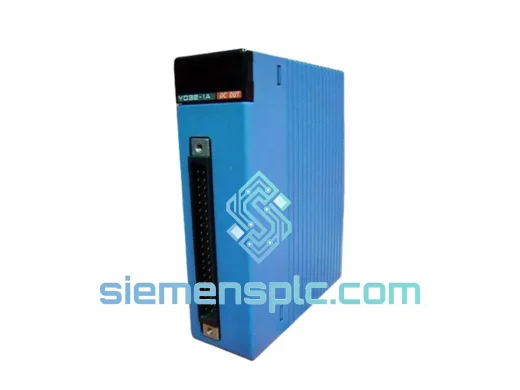
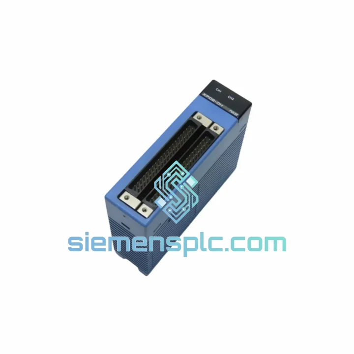
YOKOGAWA F3XP02-0H High-Speed Counter Module – FA-M3 Series
Request verified availability, condition, replacement risk review, packing options and courier lead time for F3XP02-0H.
BrandYokogawa
Part NumberF3XP02-0H
ConditionAvailability Check
Lead TimeRFQ Confirmation
DocumentsDatasheet / photos by RFQ
ShippingExport packing available
Auto-filled RFQ
F3XP02-0H
Click Request Quote and the part number is inserted into the inquiry form automatically.
- Reply by email: [email protected]
- WhatsApp / Tel: +86 18359268345
- Mon-Sat 9:00-18:00 GMT+8
Procurement Data
Key Product Information
Core fields for model confirmation and RFQ routing. Detailed product narrative remains below.
- Brand
- Yokogawa
- Primary Part Number
- F3XP02-0H
- Product Type
- High-Speed Counter Module
- Series / Family
- FA-M3
- Manufacturer
- YOKOGAWA Electric Corporation
- Country of Origin
- JP
- Catalog Category
- PLCs & Controllers
- Operating Temp.
- 0 °C to +55 °C
- Warranty
- 12 months from date of shipment
Model confirmed for inquiry
F3XP02-0H
Send quantity, destination and urgency. The RFQ form keeps this part number attached.
Request Quote
Product Overview
YOKOGAWA F3XP02-0H — Dual-Channel High-Speed Counter Module for FA-M3 Range-Free Multi-Controller
The YOKOGAWA F3XP02-0H is a dual-channel high-speed counter module engineered for the FA-M3 Range-Free Multi-Controller platform. It is designed to acquire, accumulate, and latch pulse-train signals from incremental rotary encoders, magnetic pickups, proximity switches, and flow-meter transmitters operating at frequencies up to 500 kHz per channel. In closed-loop positioning, speed-regulation, and batch-counting applications, the accuracy of pulse acquisition directly determines the fidelity of the control output. A single missed edge at high velocity translates to a measurable position error; at 500 kHz input, one missed count per second represents a 0.0002% acquisition error — a figure that compounds across multi-axis systems. The F3XP02-0H addresses this at the hardware level through dedicated ASIC-based counting logic that operates independently of the CPU scan cycle, ensuring zero-loss acquisition regardless of ladder-program execution load.
Within the FA-M3 backplane architecture, the module communicates with the CPU via the internal high-speed bus, transferring 32-bit counter values, latch registers, and status flags within a single bus arbitration cycle. This deterministic data path eliminates the jitter that would otherwise arise from software polling, making the F3XP02-0H suitable for applications where counter data must be consumed by PID or cam-profile algorithms within a fixed scan window. The module supports up to two independent counting channels, each configurable for single-phase pulse input, 90° phase-difference (quadrature A/B) input, or up/down pulse input — covering the full range of encoder interface standards encountered in machine-tool, packaging, and process-control environments.
Real-time Stock & RFQ: [email protected] | WhatsApp: +86 18359268345
Technical Parameters
| Parameter | Specification |
|---|---|
| Model Number | F3XP02-0H |
| Manufacturer | YOKOGAWA Electric Corporation |
| Series | FA-M3 Range-Free Multi-Controller |
| Module Category | High-Speed Counter Module |
| Number of Counter Channels | 2 (independent) |
| Maximum Input Frequency | 500 kHz per channel |
| Counter Resolution | 32-bit (0 to 4,294,967,295 / ±2,147,483,648 in ring/linear mode) |
| Input Signal Modes | Single-phase pulse; 90° quadrature (A/B phase); Up/Down pulse |
| Input Voltage Range | 5 V DC (TTL-compatible) / 12–24 V DC (open-collector) |
| Input Current (24 V DC) | Approx. 7 mA per input point |
| Isolation Method | Photocoupler (optical isolation) between field inputs and internal logic |
| Latch Function | Hardware latch via external Z-phase or dedicated latch input |
| Preset Function | Software-configurable preset value loaded from CPU register |
| Comparison Output | Coincidence output when counter value matches preset register |
| Internal Bus Interface | FA-M3 high-speed backplane bus (proprietary parallel bus) |
| Power Consumption (5 V internal bus) | Approx. 0.8 W |
| Operating Temperature | 0 °C to +55 °C |
| Storage Temperature | −25 °C to +70 °C |
| Relative Humidity | 10% to 90% RH (non-condensing) |
| Vibration Resistance | 10–57 Hz, 0.075 mm amplitude; 57–150 Hz, 9.8 m/s² |
| Shock Resistance | 147 m/s² (15 G), 11 ms, 3 axes |
| EMC Compliance | IEC 61131-2; CE marking |
| Module Dimensions (W × H × D) | 34.5 mm × 130 mm × 110 mm (standard FA-M3 single-slot form factor) |
| Weight | Approx. 200 g (module only) |
| Country of Origin | Japan |
| Warranty | 12 months from date of shipment |
Hardware Logical Analysis
The F3XP02-0H separates pulse acquisition from CPU execution at the silicon level. Each channel is served by a dedicated hardware counter register clocked directly from the input signal conditioning circuit, not from the CPU clock domain. This architecture means that even during a CPU scan overrun — a condition that can occur when ladder logic execution time exceeds the configured scan period — the counter continues accumulating without interruption. The CPU reads the frozen latch value at the next synchronization point, preserving count integrity across scan boundaries.
Photocoupler Isolation Architecture: Each input line passes through a high-speed photocoupler rated for signal propagation delays below 1 µs, which is the threshold required to maintain signal fidelity at 500 kHz. The isolation barrier provides a minimum 500 V DC withstand voltage between the field wiring domain and the internal 5 V logic domain. This prevents ground-loop currents — common in large machine frames where multiple earth reference points exist — from corrupting the counter logic or damaging the backplane bus.
Quadrature Decoding Logic: In A/B phase mode, the module implements hardware quadrature decoding with ×4 multiplication, meaning each full encoder cycle (four edges: A-rise, B-rise, A-fall, B-fall) increments the counter by four counts. At a mechanical resolution of 1,000 pulses per revolution, this yields an effective electrical resolution of 4,000 counts per revolution without any software interpolation overhead. Direction discrimination is performed in hardware by monitoring the phase relationship between A and B channels, with the result written directly to the count direction flag register accessible by the CPU.
EMC Design Measures: The module’s PCB layout routes high-frequency input traces with controlled impedance and places guard traces between the field-side and logic-side copper pours. Ferrite beads are placed in series with the power supply pins to attenuate conducted emissions above 1 MHz. The metal front panel is bonded to the rack chassis ground, providing a Faraday shield effect that reduces radiated susceptibility in environments with variable-frequency drives, arc welders, or high-current motor starters operating in proximity.
Latch and Preset Register Mechanism: The hardware latch input captures the instantaneous counter value into a shadow register on the rising edge of the Z-phase (index) signal, without interrupting the ongoing count. This is essential in homing sequences where the machine must record the exact position at which the encoder index pulse fires while continuing to count subsequent motion. The preset register allows the CPU to write a starting value into the counter — for example, to offset a mechanical zero reference — without stopping the count chain.
System Integration Benefits
- Zero-Loss Pulse Acquisition at 500 kHz: Hardware counting logic operates asynchronously from the CPU scan, guaranteeing no pulse is dropped regardless of ladder program complexity or scan time variation.
- Deterministic Data Delivery to Control Algorithms: Counter values are transferred to the CPU register map within a fixed bus arbitration window, allowing PID and cam-profile routines to consume fresh data every scan without polling latency.
- Dual Independent Channels in a Single Slot: Two fully independent counter channels share one backplane slot, reducing rack space consumption by 50% compared to single-channel alternatives and lowering per-axis hardware cost.
- Native FA-M3 Backplane Compatibility: The module installs into any slot of any FA-M3 CPU or expansion rack without adapter hardware, and is recognized automatically by the FA-M3 system configurator (WideField3 engineering software).
- Hardware Coincidence Output for Real-Time Interlock: The comparison output fires within one input clock cycle of the counter reaching the preset value, enabling hardware-level position interlocks that do not depend on CPU scan timing — critical for over-travel protection and cam-switch emulation.
- Flexible Input Compatibility: Accepts both TTL (5 V) and open-collector (12–24 V DC) encoder outputs without external signal converters, reducing BOM complexity during system design.
- Diagnostic Transparency via Status Registers: The module exposes input frequency, count direction, latch status, and overflow/underflow flags as readable registers, giving the CPU full visibility into counter health without additional diagnostic hardware.
- Scalable Multi-Axis Architecture: Multiple F3XP02-0H modules can be installed in the same rack, with each pair of channels independently configured. A single FA-M3 rack can host up to 16 counter channels across eight modules, supporting complex multi-axis positioning systems within a compact enclosure footprint.
- Reduced Commissioning Time: WideField3 auto-detects the module and pre-populates I/O assignment tables, eliminating manual address mapping and reducing the risk of configuration errors during system startup.
- Long-Term Parts Availability: As a current-generation FA-M3 module, the F3XP02-0H benefits from YOKOGAWA’s documented long-term supply commitment, reducing lifecycle obsolescence risk for plant assets with 10–20 year operational horizons.
Quality Assurance & Global Logistics
Every F3XP02-0H unit supplied through siemensplc.com is sourced as genuine YOKOGAWA original hardware. Each module carries YOKOGAWA’s factory serial number and production date code, which can be cross-referenced against YOKOGAWA’s traceability records. Before dispatch, our technical team performs a visual inspection covering connector pin integrity, label authenticity, firmware version marking, and physical housing condition. Units showing any sign of counterfeit labeling, pin damage, or non-original firmware are rejected and not offered for sale.
Logistics operations are based in Xiamen, China — a major international freight hub with direct air cargo connections to Singapore, Frankfurt, Los Angeles, Dubai, and Tokyo. Standard export packaging uses anti-static foam inserts within double-wall corrugated cartons, conforming to ISTA 2A transit testing standards. For time-critical orders, DHL Express and FedEx International Priority services from Xiamen typically achieve delivery to major industrial centers in Southeast Asia within 2–3 business days, Europe within 3–5 business days, and North America within 3–4 business days. All shipments include full tracking, commercial invoice, and packing list documentation required for customs clearance. A 12-month warranty covers manufacturing defects from the date of shipment.
Contact Information
Email: [email protected]
WhatsApp: +86 18359268345
Web: siemensplc.com
Location: Xiamen, China
© 2026 siemensplc.com. All rights reserved.
Ready to quote
[email protected]
Send This Part Number to Sales
RFQ workflow
Quality workflow ->
Confirmation Process
01Model confirmation
We check the full part number, brand, series and visible nameplate information before quotation.
02Availability reply
Sales confirms stock path, condition option, quantity and realistic lead time for export dispatch.
03Packing & courier
DHL, FedEx, UPS or buyer courier arrangements can be reviewed with packing requirements.
Continue sourcing
Browse full catalog ->
Related Automation Parts
Similar brand or category products for fast comparison and multi-item RFQ lists.