Yokogawa
In Stock OK
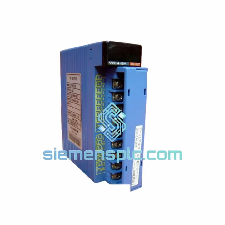
YOKOGAWA F3YD14-5A PLC Output Module – FA-M3 Series
Request verified availability, condition, replacement risk review, packing options and courier lead time for F3YD14-5A.
BrandYokogawa
Part NumberF3YD14-5A
ConditionAvailability Check
Lead TimeRFQ Confirmation
DocumentsDatasheet / photos by RFQ
ShippingExport packing available
Auto-filled RFQ
F3YD14-5A
Click Request Quote and the part number is inserted into the inquiry form automatically.
- Reply by email: [email protected]
- WhatsApp / Tel: +86 18359268345
- Mon-Sat 9:00-18:00 GMT+8
Procurement Data
Key Product Information
Core fields for model confirmation and RFQ routing. Detailed product narrative remains below.
- Brand
- Yokogawa
- Primary Part Number
- F3YD14-5A
- Product Type
- PLC Output Module
- Series / Family
- FA-M3
- Manufacturer
- YOKOGAWA Electric Corporation
- Country of Origin
- JP
- Catalog Category
- I/O Modules
- Operating Temp.
- 0 °C to +55 °C
- Warranty
- 12 months from date of shipment
Model confirmed for inquiry
F3YD14-5A
Send quantity, destination and urgency. The RFQ form keeps this part number attached.
Request Quote
Product Overview
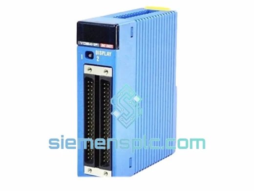
YOKOGAWA F3YD14-5A: 14-Point Sink Transistor Output Module in the FA-M3 Control Architecture
The YOKOGAWA F3YD14-5A is a 14-channel NPN (sink-type) transistor digital output module designed for deployment within the FA-M3 modular programmable controller platform. Its role in a control loop is unambiguous: it serves as the final command interface between the CPU’s logic execution layer and the field-level actuator network. Each output channel drives a discrete 24 VDC load — solenoid valves, relay coils, motor contactors, indicator lamps, or stepper motor pulse inputs — with solid-state switching that eliminates the mechanical wear inherent to relay-based alternatives.
Within the FA-M3 backplane architecture, the F3YD14-5A communicates with the CPU module via the internal high-speed bus. The FA-M3 platform employs a parallel backplane structure with a cycle time as low as 0.1 ms for I/O refresh, meaning output state changes commanded by the CPU ladder or function block program are reflected at the physical terminals within a single scan cycle. This deterministic latency characteristic is critical in applications such as servo pulse output sequencing, high-frequency valve cycling in batch reactors, or synchronized multi-axis motion coordination where output jitter directly degrades process quality.
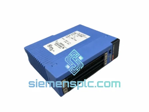
The module occupies a single slot on any FA-M3 base unit (F3BU series), drawing its logic power from the backplane supply rail. Load power for the 14 output channels is sourced externally via the module’s terminal block, allowing the field-side 24 VDC supply to be isolated from the controller’s internal logic supply — a fundamental safety and noise-isolation design principle in industrial panel engineering.
Real-time Stock & RFQ: [email protected] | WhatsApp: +86 18359268345
Technical Parameters
| Parameter | Specification |
|---|---|
| Model Number | F3YD14-5A |
| Manufacturer | YOKOGAWA Electric Corporation |
| Series | FA-M3 Programmable Controller |
| Module Category | Digital Output (DO) Module |
| Output Points | 14 channels |
| Output Transistor Type | NPN open-collector (sink) |
| Rated Load Voltage | 24 VDC |
| Maximum Load Current (per channel) | 0.5 A (refer to official datasheet for derating curve) |
| Leakage Current (OFF state) | ≤ 0.1 mA |
| Residual Voltage (ON state) | ≤ 1.5 V |
| Response Time (OFF → ON) | ≤ 1 ms |
| Response Time (ON → OFF) | ≤ 1 ms |
| Isolation Method | Photocoupler (optical isolation between logic and field side) |
| Insulation Resistance | ≥ 10 MΩ at 500 VDC |
| Dielectric Strength | 500 VAC for 1 minute (between I/O and internal bus) |
| Operating Temperature | 0 °C to +55 °C |
| Storage Temperature | -20 °C to +70 °C |
| Relative Humidity | 10% to 90% RH (non-condensing) |
| Vibration Resistance | 10–57 Hz: 0.075 mm amplitude; 57–150 Hz: 9.8 m/s² |
| Shock Resistance | 147 m/s² (15 G), 11 ms half-sine |
| Mounting | FA-M3 base unit (F3BU series) rack mount |
| Status Indicators | Per-channel LED (output ON/OFF state) |
| Module Weight | Approx. 200 g (module only) |
| Warranty | 12 months from date of shipment |
| Country of Origin | Japan |
Hardware Logical Analysis
Photocoupler Isolation Architecture: Each of the 14 output channels incorporates an individual photocoupler between the CPU-side logic signal and the field-side NPN transistor driver. This galvanic isolation barrier — rated at 500 VAC dielectric strength — prevents ground loops, transient voltage spikes from inductive load switching, and common-mode noise from propagating back into the FA-M3 backplane bus. In environments with large motor drives, welding equipment, or high-current contactors operating nearby, this isolation layer is not optional engineering — it is the primary mechanism that preserves CPU data integrity.
NPN Open-Collector Output Topology: The sink-type (NPN) configuration means the transistor’s collector is the switched terminal, and the emitter is tied to the common ground (COM) terminal. When the CPU asserts a logic HIGH on the corresponding output coil, the photocoupler activates the base of the NPN transistor, pulling the collector terminal to near-ground potential and completing the load circuit. This topology is the dominant standard in Asian and European industrial wiring practice, where PLC output commons are typically connected to the negative rail of the 24 VDC field supply.
Inductive Load Suppression: Transistor outputs driving inductive loads — solenoid valves, relay coils, motor starters — generate back-EMF transients at turn-off. The F3YD14-5A’s output stage incorporates internal flyback suppression circuitry (typically a freewheeling diode or transient voltage suppressor) to clamp these spikes below the transistor’s breakdown voltage. This extends transistor service life and prevents false triggering of adjacent channels through capacitive coupling on the terminal block wiring.
EMC Design Compliance: The module’s PCB layout follows YOKOGAWA’s internal EMC design rules, which include ground plane partitioning between the logic domain and the I/O domain, controlled impedance traces on high-speed bus interface lines, and decoupling capacitors at each power supply pin. The module housing provides shielding continuity when seated in the FA-M3 base unit, contributing to the system’s overall CE-marked EMC compliance envelope.
Backplane Bus Interface: The F3YD14-5A interfaces to the FA-M3 internal bus through the module’s edge connector. The FA-M3 bus protocol handles module identification, I/O mapping, and diagnostic status reporting. The CPU automatically detects the module type and slot position during power-up initialization, mapping the 14 output channels to consecutive coil addresses in the CPU’s I/O table. No DIP switch configuration or manual address assignment is required — the slot position determines the I/O address range.
System Integration Benefits
- Deterministic I/O Refresh Cycle: The FA-M3 backplane bus delivers I/O refresh times as low as 0.1 ms, ensuring that output state changes are applied to field devices within a single CPU scan cycle. This eliminates accumulated latency in time-critical control loops such as high-speed packaging machinery or precision dispensing systems.
- Zero-Configuration Slot Detection: The CPU module automatically identifies the F3YD14-5A by module type code during system initialization. I/O address mapping is slot-position-based, eliminating manual DIP switch configuration and reducing commissioning errors in multi-module panel builds.
- Per-Channel LED Diagnostics: Each of the 14 output channels has a dedicated status LED visible from the front panel. Maintenance personnel can verify output state without connecting a laptop or handheld programmer, reducing mean time to diagnose (MTTD) during fault-finding on the production floor.
- Galvanic Isolation for Noise Immunity: The photocoupler isolation on every channel prevents field-side electrical disturbances — including inductive kickback from solenoid valves and motor contactors — from reaching the CPU backplane bus, maintaining data integrity in electrically noisy environments.
- Solid-State Reliability: Transistor switching has no moving parts and no contact wear mechanism. In applications with high output switching frequency — such as pulse-width modulated valve control or stepper motor pulse trains — the F3YD14-5A maintains consistent switching characteristics over tens of millions of cycles without degradation.
- Compact 14-Point Density: Fourteen output points in a single FA-M3 slot reduces the number of modules required for a given I/O count, lowering base unit slot consumption, reducing panel wiring density, and decreasing overall system BOM cost compared to lower-density 8-point alternatives.
- Standardized Terminal Block Wiring: The module’s field wiring interface uses YOKOGAWA’s standard FA-M3 terminal block format, compatible with existing panel wiring harnesses and cable management systems in FA-M3 installations. This simplifies module replacement during maintenance without rewiring the field cable loom.
- Integrated Fault Reporting via CPU: The FA-M3 CPU’s diagnostic functions can detect module hardware faults (such as a missing module or backplane communication error) and report them via the system error register, enabling SCADA or HMI systems to display specific fault codes rather than generic alarm states. This diagnostic transparency reduces troubleshooting time and supports predictive maintenance workflows.
Quality Assurance & Global Logistics
Every YOKOGAWA F3YD14-5A unit supplied by siemensplc.com is sourced as genuine YOKOGAWA-manufactured hardware. YOKOGAWA Electric Corporation’s manufacturing facilities operate under ISO 9001 quality management systems, and FA-M3 series modules undergo functional testing at the factory prior to shipment. Each module carries YOKOGAWA’s original part label, revision marking, and date code — all of which are verified by our technical team upon receipt.
Our inspection process includes physical examination of the module housing, connector pin condition, PCB visible surface (where accessible), and label authenticity cross-referenced against YOKOGAWA’s official part numbering documentation. Modules that do not pass inspection are quarantined and not offered for sale.
Shipments originate from our warehouse in Xiamen, China — a major international logistics hub with direct access to DHL Express, FedEx International Priority, UPS Worldwide Express, and TNT services. Standard export documentation includes commercial invoice, packing list, and certificate of origin. For regulated destinations, we can provide additional documentation including CITES-exempt declarations and customs pre-clearance paperwork.
Typical dispatch time for in-stock units is 1–3 business days from order confirmation. International transit times via express courier are generally 3–7 business days to Europe, North America, Southeast Asia, and the Middle East. Sea freight consolidation is available for large-volume orders. All shipments include full tracking and are covered by our 12-month warranty against manufacturing defects and functional failures under normal operating conditions.
Anti-static packaging (ESD bags, foam inserts, outer carton with fragile labeling) is standard for all electronic module shipments. For temperature-sensitive destinations or extended transit routes, additional protective packaging is applied on request.
Contact Information
Email: [email protected]
WhatsApp: +86 18359268345
Web: siemensplc.com
Location: Xiamen, China
© 2026 siemensplc.com. All rights reserved.
Ready to quote
[email protected]
Send This Part Number to Sales
RFQ workflow
Quality workflow ->
Confirmation Process
01Model confirmation
We check the full part number, brand, series and visible nameplate information before quotation.
02Availability reply
Sales confirms stock path, condition option, quantity and realistic lead time for export dispatch.
03Packing & courier
DHL, FedEx, UPS or buyer courier arrangements can be reviewed with packing requirements.
Continue sourcing
Browse full catalog ->
Related Automation Parts
Similar brand or category products for fast comparison and multi-item RFQ lists.
Yokogawa
RFQ Ready
YOKOGAWA F3YD32-1A Digital Output Module
FA-M3
Origin JP
PLC Digital Output Module
Yokogawa
RFQ Ready
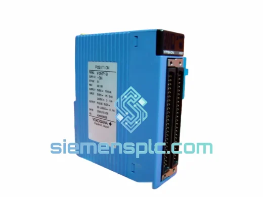
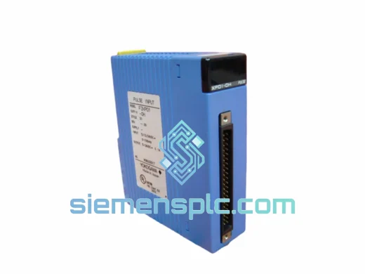
YOKOGAWA F3XP01-0H High-Speed Counter Module
FA-M3
Origin JP
High-Speed Counter Module