
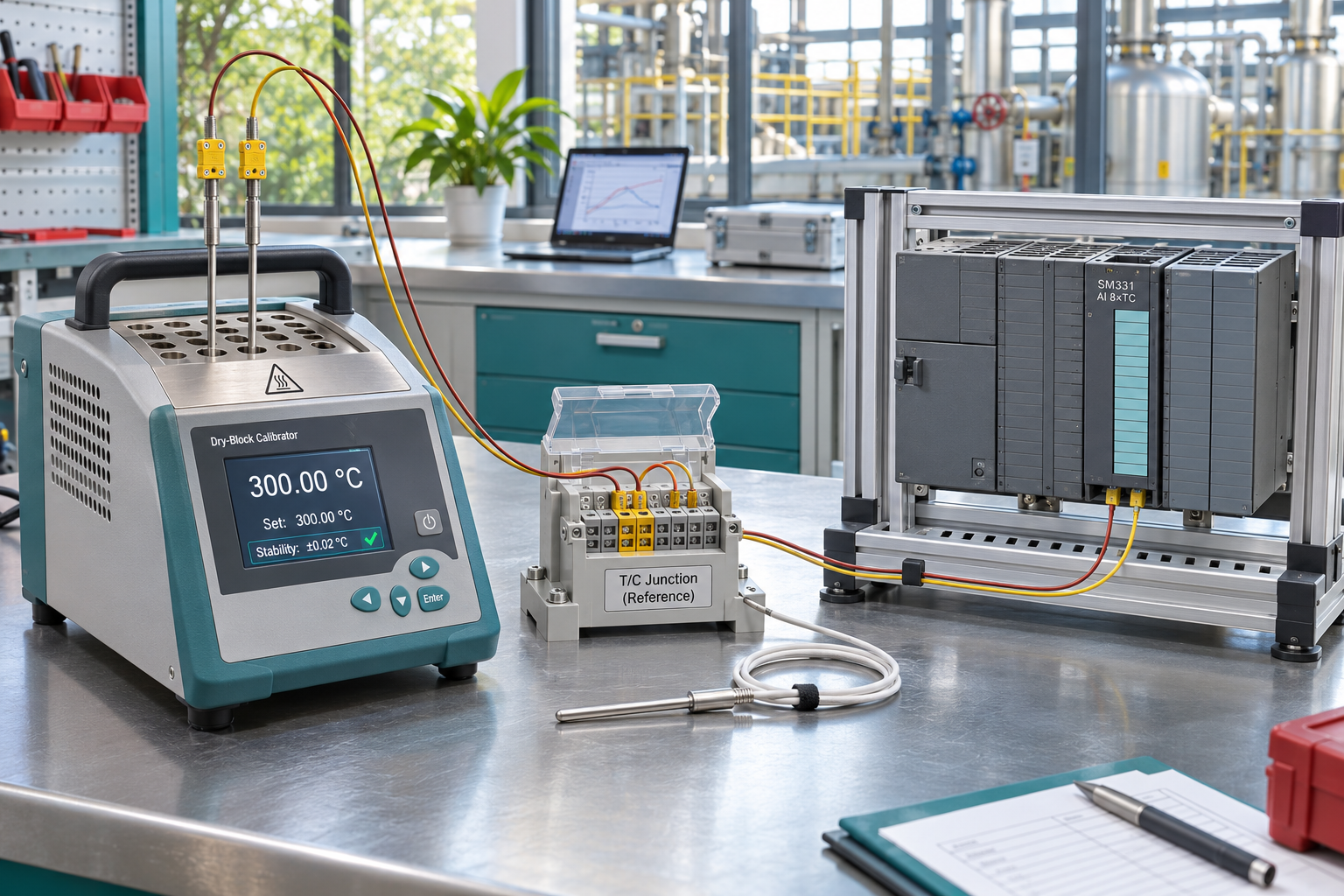
The temperature channel was believable before maintenance and is wrong after the analog card is replaced. The new module communicates, its diagnostics are not pointing to an obvious hardware failure, and the wiring appears unchanged. Before condemning the spare, check whether the measurement chain still uses the same thermocouple type, range arrangement and reference-junction compensation.
For SIMATIC S7-300 SM331 applications, the word temperature does not uniquely identify the input duty. A thermocouple produces a different kind of signal from an RTD or a temperature transmitter with a current output. Even within thermocouple applications, the reference-junction arrangement is part of the measurement. A successful card exchange must preserve that arrangement rather than merely restore communication with the rack.
The reference junction belongs in the fault boundary
A thermocouple measurement depends on the temperature difference associated with its junctions. The input system must account for the reference junction to report the intended process temperature. If the assumed reference condition differs from the actual installation, a healthy electronic input can report a misleading value. This is why a spare-card investigation should include the sensor circuit and configuration instead of treating the module as an isolated temperature meter.
Siemens’ SM331 thermocouple getting-started guide explains internal and external compensation arrangements in its example application. The lesson is to match the documented reference arrangement, thermocouple selection and module parameterization. The example is not a universal setup recipe for every SM331 order number or plant.
Read beyond the SM331 family label
For an installation identified by the full reference, the 6ES7331-7KF02-0AB0 SM331 analog input module is a specific sourcing target. Siemens’ PCS 7 catalog describes its configurable measurement functions and distinguishes it from the two-input 6ES7331-7KB02-0AB0 variant. Both support documented thermocouple duties, but their family relationship does not make them interchangeable.
If the installed station actually uses the 6ES7331-7KB02-0AB0 analog module, preserve that identity in the request. Do not replace the full code with a generic SM331 description. The exact variant, hardware revision, channel allocation and approved configuration are the basis for a spare decision.
Separate a fixed offset from an unstable measurement
Start by recording the symptom without forcing a diagnosis. Is the error similar across several related channels? Does it appear only after the cabinet warms? Is one loop noisy while the others remain consistent? Does the process indication disagree with a trustworthy independent reference? These observations help the qualified engineer choose the next check. They do not, by themselves, prove that compensation, wiring or the new card is responsible.
A useful maintenance record distinguishes the time of the hardware change from any simultaneous configuration, terminal or sensor work. When several changes occur together, attributing the result to the new card alone is unreliable. Preserve the prior approved project and the actual installed configuration. Avoid repeatedly adjusting a software offset until the display looks familiar; that can conceal a measurement-chain error and leave future maintenance with an undocumented correction.
Keep the hardware and software settings in the same record
Where the applicable module uses measuring-range selector hardware, its physical arrangement must agree with the configured measurement duty. A screenshot of software settings is therefore not the whole recovery package. Conversely, a photograph of the module does not preserve the channel’s selected thermocouple type, compensation arrangement or diagnostic settings. Retain both kinds of evidence using the manufacturer’s instructions for the exact unit.
Also preserve the approved termination and extension-cable details. A change in connection materials or the location of a reference junction can change what the system must compensate. Do not generalize from cable color alone: identify the actual sensor and extension cable using their markings and installation records. Any uncertainty should remain an engineering question, not be converted into an unsupported compatibility statement in a purchase order.
Design a check that answers the right question
A controlled input simulation and a complete sensor-loop check answer different questions. The former can help assess the configured electronic path under stated conditions. The latter addresses more of the actual installation. The responsible engineer should choose the method, reference conditions and acceptance criteria appropriate to the process. A bench demonstration is not automatically proof of the installed thermocouple system.
Use qualified personnel, approved isolation and controlled test conditions. Temperature loops may participate in important operating decisions even when the input card itself is not a safety device. Do not disconnect an active process measurement, inject a substitute signal or suppress diagnostics just to restore a plausible display. Follow the site’s procedures for handling the affected control function and returning it to service.
What a useful spare package contains
The hardware package should identify the exact module, condition and any separately supplied connection components. The recovery record should identify the approved project, channel schedule, reference-junction method and validation owner. These are complementary deliverables. A supplier may provide a functional test of the module, while the plant remains responsible for the completed measurement chain.
For stock planning, map each spare to actual installed duties. Two modules labelled temperature input may require different settings and acceptance checks. A short, maintained application note helps a future shift distinguish a ready-to-issue spare from one that needs further preparation. Review that note whenever the sensor type, wiring or approved configuration changes.
Questions after a temperature-card replacement
Does a stable but wrong temperature prove the spare is defective?
No. A stable error can arise elsewhere in the measurement chain or configuration. Preserve the observations and compare the actual installation with the approved design before assigning the cause.
Can every SM331 use the same thermocouple settings?
No. Check the full order number, applicable manual and supported functions. A family name does not specify every measurement range, channel arrangement or compensation option.
Should we copy an offset from the old project?
Preserve the approved configuration, but understand any existing correction and its documented purpose. Do not introduce or alter offsets simply to conceal an unresolved hardware or reference-junction discrepancy.
What should we send with a spare inquiry?
Provide the full module code, revision, sensor type, reference-junction arrangement, channel use and required delivery scope. Include identification photos and describe the observed error without assuming its source.
Contact [email protected] for an identified SM331 spare quotation. SiemensPLC can help clarify the supply scope; the responsible plant engineer should approve the application match and the measurement acceptance plan.
Image: AI-generated editorial illustration, not an exact product photograph or installation reference.
© 2026 SiemensPLC. All rights reserved. Official Website: https://siemensplc.com Inquiry: [email protected] | WhatsApp/Tel: +86 18359268345