ABB
In Stock OK
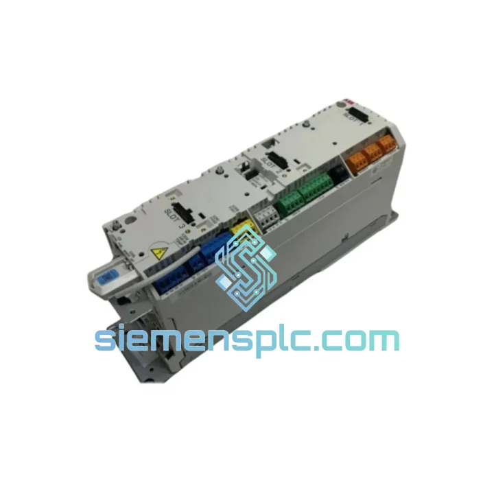
ABB ACS880-M04-014A-5 VFD Module – ACS880 Multi-Drive
Request verified availability, condition, replacement risk review, packing options and courier lead time for ACS880-M04-014A-5.
BrandABB
Part NumberACS880-M04-014A-5
ConditionAvailability Check
Lead TimeRFQ Confirmation
DocumentsDatasheet / photos by RFQ
ShippingExport packing available
Auto-filled RFQ
ACS880-M04-014A-5
Click Request Quote and the part number is inserted into the inquiry form automatically.
- Reply by email: [email protected]
- WhatsApp / Tel: +86 18359268345
- Mon-Sat 9:00-18:00 GMT+8
Procurement Data
Key Product Information
Core fields for model confirmation and RFQ routing. Detailed product narrative remains below.
- Brand
- ABB
- Primary Part Number
- ACS880-M04-014A-5
- Product Type
- Variable Frequency Drive Module
- Series / Family
- ACS880
- Country of Origin
- SE
- Catalog Category
- Motor Drives
- Warranty
- 12 months from date of shipment
- Compliance
- CE, UL, RoHS 2
Model confirmed for inquiry
ACS880-M04-014A-5
Send quantity, destination and urgency. The RFQ form keeps this part number attached.
Request Quote
Product Overview
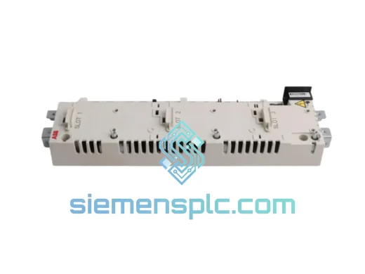
ABB ACS880-M04-014A-5: IGBT Power Module in Multi-Drive Common DC Bus Architecture
The ACS880-M04-014A-5 is a dedicated inverter power module within ABB’s ACS880 Multi-Drive platform, rated at 14 A continuous output current against a 500 V AC three-phase supply — corresponding to a 5.5 kW shaft power envelope under standard IEC load conditions. Unlike standalone single-drive units, the M04 frame module operates as a subordinate inverter cell within a shared DC bus cabinet, drawing rectified DC from a common line-side converter (LSU) and delivering independently controlled AC output to a single motor axis. This architecture eliminates per-axis rectifier redundancy, reduces total harmonic distortion (THD) at the point of common coupling (PCC), and allows regenerative energy from decelerating axes to be redistributed across the DC bus to motoring axes — a measurable efficiency gain in multi-axis coordinated motion systems.
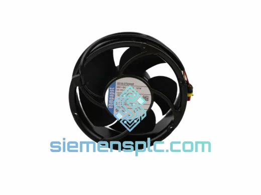
The M04 frame designation within the ACS880 series defines a specific mechanical and thermal envelope. The module mounts on a common backplane rail inside the ACS880 Multi-Drive cabinet, with DC bus bars connecting directly to the cabinet’s positive and negative rails. Output terminals feed through cabinet-side motor cable glands. The integrated forced-air cooling fan draws ambient air through the heatsink fin array, maintaining junction temperatures within IGBT safe operating area (SOA) limits across the full 14 A continuous duty cycle. Thermal derating curves published in ABB’s ACS880 hardware manual specify output current reduction above 40°C ambient — a parameter that must be factored into cabinet thermal design for installations in non-air-conditioned enclosures.
The IGBT switching stage employs a three-phase, two-level voltage source inverter (VSI) topology. Gate drive circuits are galvanically isolated from the control logic plane via optocoupler barriers rated to withstand the common-mode voltage transients inherent in PWM switching at industrial bus voltages. This isolation architecture is not merely a regulatory checkbox — it is the primary mechanism preventing high-frequency ground currents from propagating into the control signal layer, which would otherwise manifest as erratic encoder feedback, fieldbus communication errors, or nuisance STO trips in safety-rated installations.
Motor control is executed by the paired ACS880 Drive Control Unit (DCU), which implements ABB’s Direct Torque Control (DTC) algorithm. DTC operates without a modulation stage: torque and flux are estimated from measured stator currents and DC bus voltage, then controlled directly by selecting optimal inverter switching states from a pre-computed lookup table. The result is torque response times below 1 ms — approximately 10× faster than conventional space-vector PWM (SVPWM) schemes — without requiring a shaft encoder. For applications such as winder tension control, crane anti-sway, or extruder pressure regulation, this response characteristic is a functional requirement, not a performance luxury.
Real-time Stock & RFQ: [email protected] | WhatsApp: +86 18359268345
Technical Parameters
| Parameter | Value |
|---|---|
| Model / SKU | ACS880-M04-014A-5 |
| Brand | ABB |
| Series | ACS880 Multi-Drive |
| Frame Size | M04 |
| Continuous Output Current | 14 A |
| Rated Motor Power (400 V) | 5.5 kW |
| Rated Motor Power (500 V) | 5.5 kW |
| Supply Voltage Range | 380–500 V AC, 3-phase, ±10% |
| DC Bus Voltage (nominal) | 537–706 V DC |
| Switching Topology | 3-phase 2-level IGBT VSI |
| PWM Frequency (default) | 4 kHz (adjustable 2–12 kHz with derating) |
| Overload Capacity | 150% × IN for 60 s (heavy-duty cycle) |
| Protection Class | IP20 (cabinet-mount) |
| Cooling Method | Forced air, integrated fan |
| Ambient Operating Temperature | 0°C to +40°C (derate above 40°C) |
| Storage Temperature | -40°C to +70°C |
| Relative Humidity | ≤95% RH, non-condensing |
| Altitude (no derating) | ≤1000 m above sea level |
| EMC Standard | IEC/EN 61800-3, Category C3 |
| Safety Function | STO (Safe Torque Off) per IEC 61800-5-2, SIL 3 / PLe |
| Compliance | CE, UL, RoHS 2 |
| Approximate Weight | 5.6 kg |
| Warranty | 12 months from date of shipment |
Hardware Logical Analysis
The ACS880-M04-014A-5 implements several hardware-level design decisions that distinguish it from generic inverter modules in the same power class.
DC Bus Isolation and Common-Mode Rejection: The module’s DC input stage connects directly to the cabinet bus bars without an intermediate rectifier bridge. This eliminates the six-pulse rectifier commutation notches that would otherwise appear on the DC rail in a standalone drive configuration. The result is a cleaner DC bus voltage with lower ripple amplitude, which reduces the RMS current stress on DC bus capacitors and extends their service life — a critical factor in 24/7 continuous-duty installations.
IGBT Gate Drive Architecture: Each of the six IGBT switches in the three-phase bridge is driven by an isolated gate driver circuit. The isolation barrier is implemented using high-speed optocouplers with propagation delay matched to within ±50 ns across all six channels. Matched propagation delay is essential for preventing shoot-through conditions during dead-time transitions, particularly at elevated PWM frequencies where dead-time intervals are a larger fraction of the switching period.
EMC Design — Conducted and Radiated Emissions: The M04 frame includes an integrated EMC filter on the DC bus input, suppressing high-frequency conducted emissions that would otherwise propagate back through the DC bus to other inverter modules sharing the same cabinet. The filter topology uses a combination of X-capacitors across the bus rails and Y-capacitors to the cabinet ground plane, providing attenuation in the 150 kHz–30 MHz range per CISPR 11 Class A limits. For installations requiring Class B compliance, an external line filter on the LSU input is required.
Thermal Management and IGBT SOA Protection: The heatsink is extruded aluminum with a fin pitch optimized for the integrated fan’s airflow velocity. An NTC thermistor embedded in the heatsink base feeds the module’s thermal model, which continuously estimates IGBT junction temperature based on measured output current and switching frequency. If estimated junction temperature approaches the 125°C limit, the control unit reduces PWM frequency or output current before triggering a fault — a predictive derating strategy that avoids hard thermal shutdowns during transient overload events.
STO Safety Circuit: The Safe Torque Off function is implemented as a dual-channel hardware circuit, independent of the main control processor. Both STO input channels must be simultaneously de-energized to disable the IGBT gate drive signals. The circuit achieves a PFH (Probability of dangerous Failure per Hour) consistent with SIL 3 classification, verified by ABB’s functional safety assessment per IEC 61508. This architecture allows the module to be integrated into safety-rated machine control systems without additional external safety relays for the STO function.
System Integration Benefits
- Shared DC Bus Energy Recovery: Regenerative braking energy from decelerating axes is fed back to the common DC bus and consumed by simultaneously motoring axes, reducing net energy drawn from the supply — measurable as a reduction in kWh consumption in coordinated multi-axis applications such as winder-unwinder pairs.
- Reduced Cabinet Footprint: A single line-side converter (LSU) serves multiple M04 inverter modules, eliminating per-axis input rectifiers, AC contactors, and individual EMC filters. This reduces cabinet volume by 30–40% compared to an equivalent number of standalone drives.
- Deterministic Torque Response via DTC: The paired DCU’s Direct Torque Control algorithm delivers torque step response below 1 ms without encoder feedback, enabling precise tension control in winding applications and accurate speed regulation in conveyor synchronization without the latency introduced by SVPWM modulation stages.
- Unified Diagnostics via DriveComposer: All modules in the ACS880 Multi-Drive cabinet are accessible through ABB’s DriveComposer PC tool over a single fieldbus connection. Fault logs, parameter sets, and real-time signal monitoring are available for each axis without physical access to individual modules.
- Fieldbus Protocol Flexibility: The DCU supports PROFIBUS DP, PROFINET, EtherNet/IP, Modbus TCP, and CANopen via plug-in adapter modules (RDCO, FENA series), allowing the ACS880 system to integrate into existing plant automation networks without protocol conversion gateways.
- Scalable Axis Count: Additional M04 modules can be added to an existing ACS880 cabinet (within LSU capacity limits) without modifying the cabinet’s power infrastructure — a significant advantage during phased production line expansions.
- STO Integration with Safety PLCs: The dual-channel STO inputs are directly compatible with safety PLC output modules (e.g., Siemens ET 200SP F-DQ, Pilz PNOZ), eliminating the need for intermediate safety relays and simplifying the safety circuit validation documentation.
- Predictive Maintenance Data: The module’s thermal model and IGBT operating hour counters provide data accessible via the DCU parameter interface, enabling condition-based maintenance scheduling rather than fixed-interval replacement — reducing both unplanned downtime and unnecessary preventive maintenance costs.
Quality Assurance & Global Logistics
Every ACS880-M04-014A-5 unit supplied by siemensplc.com is sourced through verified ABB distribution channels. Units are inspected against ABB’s published nameplate data, label authenticity criteria, and firmware version records prior to dispatch. Anti-static packaging with shock-absorbing foam inserts protects the IGBT module and gate drive PCBs during international transit — a non-negotiable requirement given the sensitivity of power semiconductor assemblies to electrostatic discharge and mechanical shock.
Shipments originate from our warehouse in Xiamen, China. Xiamen’s port infrastructure and direct air freight connections to major industrial hubs in Europe, Southeast Asia, the Middle East, and the Americas enable consistent transit times: 3–5 business days by express air freight (DHL, FedEx, UPS) to most destinations. Sea freight consolidation is available for bulk orders. Full export documentation — commercial invoice, packing list, certificate of origin, and material safety data sheet where applicable — is prepared for each shipment to facilitate customs clearance without delay. A 12-month warranty from the date of shipment covers manufacturing defects under normal operating conditions.
Contact Information
Email: [email protected]
WhatsApp: +86 18359268345
Web: siemensplc.com
Location: Xiamen, China
© 2026 siemensplc.com. All rights reserved.
Ready to quote
[email protected]
Send This Part Number to Sales
RFQ workflow
Quality workflow ->
Confirmation Process
01Model confirmation
We check the full part number, brand, series and visible nameplate information before quotation.
02Availability reply
Sales confirms stock path, condition option, quantity and realistic lead time for export dispatch.
03Packing & courier
DHL, FedEx, UPS or buyer courier arrangements can be reviewed with packing requirements.
Continue sourcing
Browse full catalog ->
Related Automation Parts
Similar brand or category products for fast comparison and multi-item RFQ lists.