ABB
In Stock OK
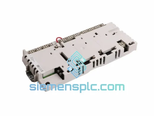
ABB SAFT 113 POW Power Supply Board – SAFT Series
Request verified availability, condition, replacement risk review, packing options and courier lead time for SAFT 113 POW.
BrandABB
Part NumberSAFT 113 POW
ConditionAvailability Check
Lead TimeRFQ Confirmation
DocumentsDatasheet / photos by RFQ
ShippingExport packing available
Auto-filled RFQ
SAFT 113 POW
Click Request Quote and the part number is inserted into the inquiry form automatically.
- Reply by email: [email protected]
- WhatsApp / Tel: +86 18359268345
- Mon-Sat 9:00-18:00 GMT+8
Procurement Data
Key Product Information
Core fields for model confirmation and RFQ routing. Detailed product narrative remains below.
- Brand
- ABB
- Primary Part Number
- SAFT 113 POW
- Product Type
- Drive Control Power Supply Board
- Series / Family
- S800
- Manufacturer
- ABB
- Country of Origin
- SE
- Catalog Category
- Motor Drives
- Operating Temp.
- 0 °C to +55 °C (forced-air cooled)
- Warranty
- 12 months from shipment date
Model confirmed for inquiry
SAFT 113 POW
Send quantity, destination and urgency. The RFQ form keeps this part number attached.
Request Quote
Product Overview
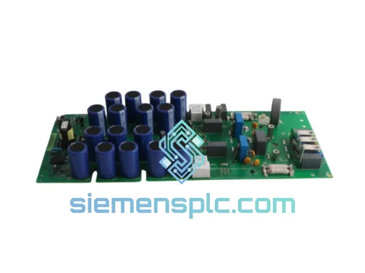
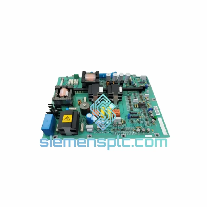
ABB SAFT 113 POW: Multi-Rail DC Power Distribution in Variable-Frequency Drive Control Architectures
The ABB SAFT 113 POW is a dedicated multi-rail DC power supply board designed for integration within ABB’s SAFT-series drive control platforms, specifically the ACS 600 and ACS 800 variable-frequency drive families. Its function within the control hierarchy is precise: it accepts an auxiliary DC bus input from the drive’s internal power stage, conditions it through a forward-converter topology, and distributes regulated voltage rails to the control logic board, gate driver circuits, and I/O interface layers. This is not a general-purpose switch-mode supply adapted for industrial use — it is an OEM-specified subsystem engineered to ABB’s internal backplane voltage sequencing and fault-isolation requirements.
Within a standard ACS 800 cabinet, the SAFT 113 POW occupies the designated power supply slot of the RDCO or AINT interface stack. Its output rails — +5 VDC for control logic, ±15 VDC for analog measurement circuits, and +24 VDC for gate driver bias — are each independently regulated and independently protected. The board’s physical form factor uses a direct plug-in backplane connector, eliminating the need for discrete wiring between the power supply and downstream boards. This connector-based integration is a deliberate design choice: it reduces contact resistance variability, eliminates field wiring errors, and allows board-level replacement without disturbing adjacent assemblies.
The SAFT 113 POW is not interchangeable with generic industrial power supplies. Its output rail sequencing, connector pinout, and protection circuit behavior are matched to the specific initialization and fault-handling logic of the ACS 600 and ACS 800 control boards. Substituting a non-OEM supply risks undefined logic states during power-on, incorrect gate driver bias timing, and loss of diagnostic signal integrity — failure modes that may not be immediately apparent but will degrade drive reliability over time.
Applications for the SAFT 113 POW span process industries where ACS 800 drives are deployed in demanding continuous-duty cycles: petrochemical pump and compressor drives, cement mill main drives, paper machine section drives, and steel rolling mill auxiliary drives. In these environments, control power supply reliability is a maintenance priority, and the availability of genuine OEM replacement boards with documented specifications is a procurement requirement rather than a preference.
Real-time Stock & RFQ: [email protected] | WhatsApp: +86 18359268345
Technical Parameters
| Parameter | Specification |
|---|---|
| Part Number | SAFT 113 POW |
| Manufacturer | ABB |
| Product Series | SAFT Series |
| Board Function | Multi-rail DC power conditioning and distribution |
| Input Voltage Range | 24–48 VDC (auxiliary DC bus tap) |
| Output Rail 1 | +5 VDC — control logic supply |
| Output Rail 2 | ±15 VDC — analog measurement and op-amp supply |
| Output Rail 3 | +24 VDC — gate driver bias supply |
| Conversion Topology | Forward converter with synchronous rectification |
| Conversion Efficiency | >85% at rated load |
| Output Ripple (+5 VDC) | <20 mV peak-to-peak at full load |
| Overcurrent Response Time | <2 µs (latching shutdown per rail) |
| Overvoltage Clamp (+24 VDC) | TVS diode, 28 V clamp voltage |
| Operating Temperature | 0 °C to +55 °C (forced-air cooled) |
| Storage Temperature | −40 °C to +70 °C |
| Relative Humidity | 5–95% RH, non-condensing |
| PCB Standard | IPC-A-610 Class 2 |
| Isolation Standard | Reinforced isolation per IEC 61800-5-1 |
| EMC Compliance | CE marked; EN 61800-3 Category C2 |
| Conducted Emission Attenuation | 150 kHz–30 MHz (CM choke + X/Y capacitor network) |
| Capacitor MTBF | >100,000 hours at 40 °C (MIL-HDBK-217F) |
| Compatible Platforms | ABB ACS 600, ACS 800, SAFT-series control stacks |
| Form Factor | Plug-in PCB module, direct backplane connector |
| Weight | Approx. 4,340 g (with mounting hardware) |
| Country of Origin | Germany |
| Condition | New, genuine ABB OEM |
| Warranty | 12 months from shipment date |
Hardware Logical Analysis
The SAFT 113 POW’s internal circuit architecture addresses three distinct failure domains that are common in drive control power supplies: rail sequencing faults, conducted EMI coupling, and protection circuit latency. Each is handled at the hardware level rather than through firmware, which is a deliberate design choice for a component that must operate correctly before any software stack is initialized.
Rail Startup Sequencing: The board implements a discrete-logic power-good sequencing circuit that enforces a fixed startup order: +5 VDC is established first, followed by ±15 VDC, and finally +24 VDC. This sequence matches the initialization dependency chain of the ACS 800 control board — the DSP and FPGA on the control board require stable +5 VDC before their internal PLLs lock, and the gate driver ICs require stable ±15 VDC before the +24 VDC bias is applied. Violating this sequence can cause latch-up in CMOS logic or undefined gate driver output states. Because the sequencing is implemented in discrete logic (comparators and RC delay networks), it is immune to firmware corruption and operates identically across all power cycles.
EMC Architecture — Split Ground Plane and CM Filter: The input stage incorporates a common-mode choke wound on a high-permeability ferrite core, in series with an X/Y capacitor filter network. This combination attenuates conducted emissions in the 150 kHz–30 MHz band to levels consistent with EN 55011 Class A. The PCB layout uses a split ground plane strategy: the switching node and primary-side circuitry are confined to a dedicated copper island, separated from the analog ground plane by a physical gap. The two planes are connected at a single star point located at the output filter capacitor bank. This topology prevents switching-frequency ground currents from coupling into the ±15 VDC analog supply rails, which feed the current measurement op-amps on the AINT interface board. Noise on these rails directly affects current feedback accuracy and, by extension, torque control precision.
Per-Rail Overcurrent Protection: Each output rail has an independent current-sense resistor and comparator circuit. When rail current exceeds the threshold, the comparator triggers a latching shutdown of that rail’s switching element within 2 µs. The latch is implemented in hardware and can only be cleared by cycling the primary input power — there is no software reset path. This design ensures that overcurrent events are not silently cleared by a watchdog or firmware restart, which is important in applications where a downstream short circuit (e.g., a failed gate driver IC) must be identified and corrected before the drive is returned to service.
Overvoltage Protection on the +24 VDC Rail: The +24 VDC gate driver supply is protected by a transient voltage suppressor (TVS) diode with a 28 V clamp voltage. This clamp absorbs inductive kickback from relay coils and solenoids connected to the +24 VDC bus, preventing voltage spikes from propagating into the gate driver ICs. The TVS is rated for repetitive transient absorption, not just single-event protection, which is relevant in applications where relay switching occurs frequently.
Capacitor Selection and Thermal Derating: Output filter capacitors are 105 °C-rated low-ESR polymer types. At the board’s maximum operating temperature of 55 °C ambient, the capacitor junction temperature remains well below the 105 °C rating, resulting in a calculated MTBF exceeding 100,000 hours per MIL-HDBK-217F Part Stress Analysis. The low-ESR characteristic of polymer capacitors reduces output ripple on the +5 VDC rail to below 20 mV peak-to-peak at full load, maintaining adequate noise margin for the control board’s FPGA I/O voltage thresholds.
System Integration Benefits
- Hardware-Enforced Rail Sequencing: Discrete-logic startup sequencing eliminates undefined logic states during drive initialization, removing a class of commissioning faults that are difficult to reproduce and diagnose in field conditions.
- Per-Rail Fault Isolation: Independent latching overcurrent protection per output rail ensures that a fault on the +24 VDC gate driver supply does not collapse the +5 VDC logic rail. The control board retains power, preserving fault log data and communication capability during and after a fault event.
- Diagnostic Signal Transparency: Power-good outputs for each rail are routed to the main control board’s status register. The drive’s diagnostic software can identify which specific rail has failed without requiring external measurement equipment, reducing fault diagnosis time in field maintenance scenarios.
- Direct Backplane Integration: The plug-in backplane connector eliminates discrete field wiring between the power supply and downstream boards. Board replacement requires no rewiring, reducing mean time to repair (MTTR) and eliminating the risk of wiring errors during maintenance.
- EMC-Compliant Conducted Emission Profile: The board’s conducted emission performance meets EN 61800-3 Category C2 without requiring additional external line filters beyond those specified in the drive’s standard installation documentation.
- Wide Input Voltage Tolerance: The 24–48 VDC input range accommodates auxiliary bus voltage variation during regenerative braking transients, preventing nuisance shutdowns in high-inertia load applications such as centrifuges, large fans, and winding machines.
- Cross-Frame Compatibility: A single SAFT 113 POW board covers power supply requirements across multiple ACS 600 and ACS 800 frame sizes, reducing the number of distinct spare part numbers that maintenance teams must stock for mixed drive fleets.
- Analog Supply Noise Isolation: The split ground plane architecture and star-point grounding strategy isolate the ±15 VDC analog supply from switching-frequency ground currents, maintaining current measurement accuracy and torque control precision in closed-loop drive applications.
- Inductive Load Transient Absorption: The TVS clamp on the +24 VDC rail provides repetitive transient absorption for relay and solenoid switching loads, protecting gate driver ICs from voltage spikes without requiring external suppression components.
- Long-Term Component Reliability: 105 °C-rated polymer capacitors with calculated MTBF exceeding 100,000 hours at 40 °C ambient reduce the probability of capacitor-related failures over the drive’s service life, supporting predictive maintenance intervals based on documented reliability data.
Quality Assurance & Global Logistics
Each SAFT 113 POW unit supplied through siemensplc.com is genuine ABB OEM stock, sourced through verified supply channels with traceability to ABB’s manufacturing records. Units are not remanufactured, reconditioned, or sourced from unverified secondary markets. Prior to shipment, each board is subject to a functional verification procedure covering output rail voltages under load, startup sequencing behavior, and protection circuit response. A test record is available upon request for applications requiring documented acceptance criteria.
ESD packaging follows IEC 61340-5-1: boards are sealed in anti-static poly bags with humidity indicator cards, placed in conductive foam-lined inner cartons, and outer-packed in double-wall corrugated export cartons rated for international air and sea freight handling. All cartons are labeled with part number, serial number, and handling instructions in English and Chinese.
Shipments originate from our warehouse in Xiamen, China, with access to DHL Express, FedEx International Priority, UPS Worldwide Express, and consolidated sea freight services. Standard export documentation — commercial invoice, packing list, and certificate of origin — is included with every shipment. CE declaration of conformity and ABB factory certificates can be arranged at order confirmation for applications requiring regulatory documentation. Typical transit times: 3–5 business days to Europe and North America via express air freight; 7–14 business days via standard air freight. Cargo insurance is included on all shipments. A 12-month warranty applies from the shipment date, covering manufacturing defects and component failure under normal operating conditions. Warranty claims receive an initial response within 48 business hours.
Contact Information
Email: [email protected]
WhatsApp: +86 18359268345
Web: siemensplc.com
Location: Xiamen, China
© 2026 siemensplc.com. All rights reserved.
Ready to quote
[email protected]
Send This Part Number to Sales
RFQ workflow
Quality workflow ->
Confirmation Process
01Model confirmation
We check the full part number, brand, series and visible nameplate information before quotation.
02Availability reply
Sales confirms stock path, condition option, quantity and realistic lead time for export dispatch.
03Packing & courier
DHL, FedEx, UPS or buyer courier arrangements can be reviewed with packing requirements.
Continue sourcing
Browse full catalog ->
Related Automation Parts
Similar brand or category products for fast comparison and multi-item RFQ lists.
ABB
RFQ Ready
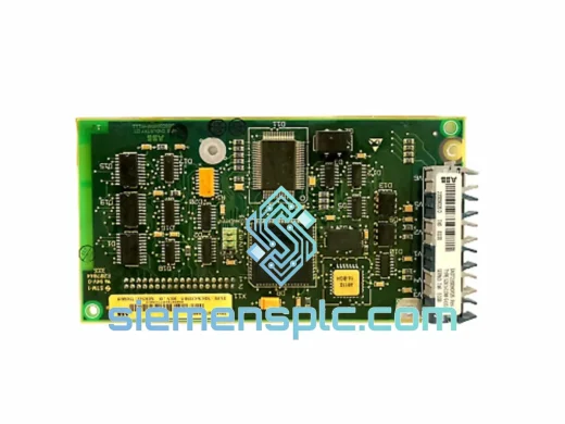
ABB SDCS-COM-5 3BSE006567R1 Fieldbus Communication Module
S800
Origin SE
Fieldbus Communication Module
ABB
RFQ Ready
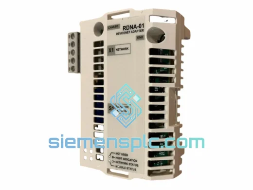
ABB RDNA-01 DeviceNet Adapter Module – ACS800 ACS600
S800
Origin SE
Fieldbus Communication Module
ABB
RFQ Ready
ABB RDCU-12C 3AUA0000036521 Drive Control Unit
S800
Origin SE
PLC & Drive Control Module