Siemens
RFQ Ready
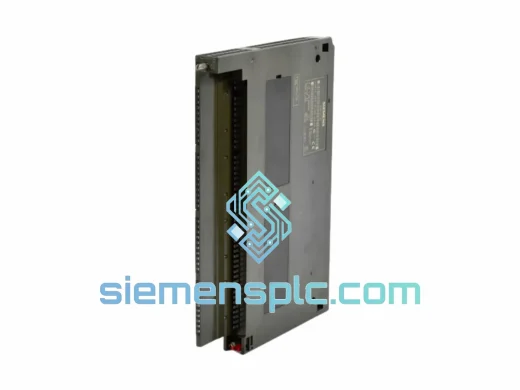
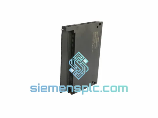
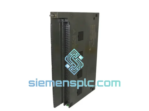
Siemens 6ES7431-1KF00-0AB0 Analog Input Module
SIMATIC S7-400
Origin DE
PLC Analog Input Module
Request verified availability, condition, replacement risk review, packing options and courier lead time for 6ES7421-1BL01-0AA0.
Click Request Quote and the part number is inserted into the inquiry form automatically.
Core fields for model confirmation and RFQ routing. Detailed product narrative remains below.
In large-scale process automation, the digital input module is the primary sensory interface between the physical plant and the control system’s decision logic. The 6ES7421-1BL01-0AA0 performs this function within the SIMATIC S7-400 architecture: it acquires 32 discrete 24 V DC field signals per rack slot, conditions each channel through an optocoupler isolation stage, and transfers validated binary state data across the P-bus backplane to the CPU within a deterministic scan cycle. Every design decision in this module — from its group-isolation topology to its four-step adjustable input filter — reflects the engineering constraints of continuous-process environments where signal integrity and diagnostic transparency are non-negotiable.
The S7-400 platform targets applications that exceed the capacity of mid-range controllers: refinery distributed control integration, automotive transfer-line sequencing, power plant auxiliary systems, and pharmaceutical batch reactors. Within this platform, the 6ES7421-1BL01-0AA0 occupies the high-density input tier. At 32 channels per single-width slot (25 mm rack pitch), it delivers the lowest cost-per-channel of any S7-400 digital input module, while maintaining the electrical isolation and diagnostic depth that safety-instrumented and high-availability systems require. Field installations span petrochemical complexes in the Middle East, automotive body shops in Central Europe, and water treatment facilities across Southeast Asia — environments where this module has accumulated a multi-decade reliability record under sustained thermal and vibration stress.
📦 Real-time Stock & RFQ: [email protected] | WhatsApp: +86 18359268345
| Parameter | Value |
|---|---|
| Number of digital inputs | 32 |
| Rated input voltage | 24 V DC |
| Signal “1” voltage range | 15 V DC to 30 V DC |
| Signal “0” voltage range | 0 V DC to 5 V DC |
| Input current at rated voltage | approx. 7 mA per channel |
| Input filter delay (selectable) | 0.1 ms / 0.5 ms / 3 ms / 15 ms |
| Galvanic isolation | Group isolation, 16 channels per group; 500 V AC between groups and backplane |
| Backplane bus current draw | max. 100 mA at 5 V DC (via S7-400 P-bus) |
| Power dissipation | max. 3.5 W |
| Front connector | 48-pin (order separately: 6ES7492-1AL00-0AA0) |
| Module width | 25 mm (single-width S7-400 slot) |
| Dimensions (W × H × D) | 25 mm × 290 mm × 210 mm |
| Weight | approx. 600 g |
| Operating temperature | 0 °C to +60 °C |
| Storage temperature | −40 °C to +70 °C |
| Relative humidity | 10 % to 95 %, non-condensing (IEC 60068-2-30) |
| Vibration resistance | 10–58 Hz / 0.075 mm; 58–150 Hz / 1 g (IEC 60068-2-6) |
| Degree of protection | IP20 |
| Input characteristic | IEC 61131-2 Type 1 (24 V DC, current-sinking) |
| Certifications | CE, UL, cUL, FM, ATEX Zone 2 |
| Compatible racks | S7-400 UR1, UR2, UR2-H, ER1, ER2 |
| Warranty | 12 months from date of shipment |
Optocoupler Isolation Architecture
Each of the 32 input channels passes through a dedicated optocoupler stage before the signal reaches the module’s internal logic. The optocoupler physically breaks the conductive path between the field wiring and the backplane bus, establishing a 500 V AC isolation barrier per channel group (16 channels per group). This topology serves two distinct engineering purposes: it prevents ground-loop currents — common in large plants where field cable runs span multiple earthing zones — from corrupting the binary state read by the CPU, and it limits the propagation of field-side transient energy (inductive switching spikes, lightning-induced surges on long cable runs) to within the isolated group rather than allowing it to reach the backplane and affect adjacent modules or the CPU itself.
Adjustable Input Filter — Debounce Without External Hardware
The four-step input filter (0.1 ms / 0.5 ms / 3 ms / 15 ms) is implemented in the module’s ASIC-level signal conditioning layer, not in CPU firmware. This distinction matters: the filter operates independently of the CPU scan cycle, meaning debounce is applied before the signal is latched onto the P-bus. At 0.1 ms, the module can track high-frequency discrete events — encoder index pulses, high-speed proximity sensor outputs — without aliasing. At 15 ms, it suppresses contact bounce from mechanical limit switches and pushbutton stations, eliminating the need for external RC filter networks on the terminal block. The filter setting is configured via STEP 7 hardware configuration and stored in the module’s parameter memory, surviving power cycles without re-download.
EMC Design and Conducted Immunity
The module’s PCB layout follows Siemens’ internal EMC design rules for industrial-grade products: signal traces are routed with controlled impedance, the optocoupler stage provides common-mode rejection, and the backplane connector interface is shielded against radiated emissions from adjacent power modules. The module meets EN 61000-4-4 (electrical fast transient/burst) and EN 61000-4-5 (surge) immunity levels required for industrial environments, validated through Siemens’ type-test certification process. In practice, this means the module maintains correct input state reporting in the presence of variable-frequency drive switching noise, solenoid valve coil collapse transients, and arc-flash events on adjacent field circuits — conditions routinely encountered in process plant electrical environments.
P-Bus Data Transfer and Scan Cycle Integration
The 6ES7421-1BL01-0AA0 communicates with the S7-400 CPU via the parallel P-bus backplane, which operates at a fixed transfer rate independent of the number of modules installed. The module presents its 32-bit input image to the CPU at each scan cycle boundary; the CPU reads the process image input (PII) table in a single atomic operation, ensuring that all 32 channels reflect a consistent snapshot of field state at the same point in the scan. This eliminates the race condition that would arise if channels were read sequentially — a critical property for interlock logic where multiple input states must be evaluated as a coherent set.
Every 6ES7421-1BL01-0AA0 unit dispatched from our Xiamen, China facility is a genuine Siemens-manufactured component sourced through verified supply channels. Authenticity verification includes cross-referencing the module’s serial number and date code against Siemens product lifecycle records, inspecting the holographic label and housing markings for conformance to Siemens’ current production standards, and confirming firmware version compatibility with the customer’s target CPU revision.
Pre-shipment functional testing seats the module in an S7-400 test rack, exercises all 32 input channels with calibrated 24 V DC test signals across the full filter-delay range, and verifies diagnostic interrupt generation. A written test report is issued for each unit and included with the shipment documentation package, which also contains the original Siemens product datasheet, a certificate of conformity, and a packing list with net/gross weight and HS code declaration for customs clearance.
Logistics from Xiamen reach major industrial hubs efficiently: DHL Express and FedEx International Priority services deliver to Western Europe in 3–5 business days, to North America in 4–6 business days, and to Southeast Asia in 1–3 business days. For project-volume orders, sea freight consolidation and air freight charter options are available. Export documentation — commercial invoice, packing list, certificate of origin, and ATEX declaration where required — is prepared to the destination country’s import requirements. DDP (Delivered Duty Paid) and DAP (Delivered At Place) Incoterms are both supported.
📧 Email: [email protected]
💬 WhatsApp: +86 18359268345
🌐 Web: siemensplc.com
📍 Location: Xiamen, China
© 2026 siemensplc.com. All rights reserved.
We check the full part number, brand, series and visible nameplate information before quotation.
Sales confirms stock path, condition option, quantity and realistic lead time for export dispatch.
DHL, FedEx, UPS or buyer courier arrangements can be reviewed with packing requirements.
Similar brand or category products for fast comparison and multi-item RFQ lists.