Allen-Bradley
RFQ Ready
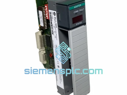
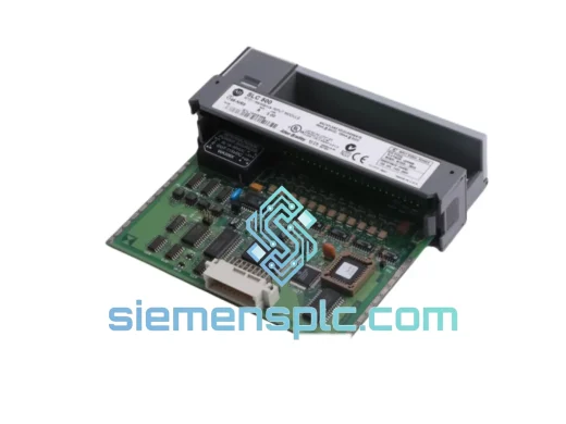
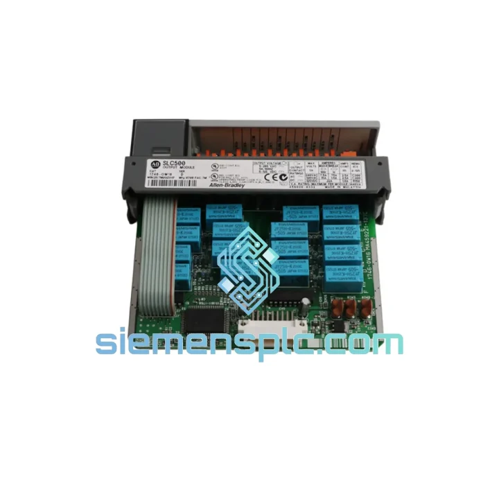
Allen-Bradley AIM16 PLC Input Module – SLC 500 Series
SLC 500
Origin US
PLC Input Module
Request verified availability, condition, replacement risk review, packing options and courier lead time for 1746-OW16.
Click Request Quote and the part number is inserted into the inquiry form automatically.
Core fields for model confirmation and RFQ routing. Detailed product narrative remains below.
The 1746-OW16 is a 16-point relay contact discrete output module designed for the Allen-Bradley SLC 500 Modular I/O platform. It occupies a single chassis slot and delivers galvanically isolated switching across a broad load voltage range of 5–265 V AC and 5–125 V DC, making it the standard selection for control panels that must drive mixed-voltage field devices from a single output card. In process industries, automotive assembly, and infrastructure automation, the relay contact architecture of this module provides a level of electrical separation between the PLC backplane and field wiring that solid-state output technologies cannot replicate without external isolation relays.
Within the SLC 500 I/O hierarchy, the 1746-OW16 addresses the density gap between the 8-point 1746-OW8 and the triac-based 1746-OA16. Its 16 normally-open relay contacts are organized into two groups of eight, each group sharing a common terminal and protected by an individual fuse. This group architecture limits fault propagation: a shorted field device blows one group fuse and leaves the remaining eight outputs operational, preserving partial control authority during fault diagnosis without requiring a full module swap. The removable terminal block (RTB) design further reduces mean time to repair—field wiring stays connected to the RTB while the module body is exchanged, eliminating rewiring time entirely.
The module communicates with the SLC 500 processor via the 1746 parallel backplane at 5 V DC, drawing 125 mA from the chassis power supply. Output state data is mapped directly into the processor’s output image table as a contiguous 16-bit word, with no additional configuration required beyond slot addressing in RSLogix 500. This transparent I/O mapping means ladder logic written for an 8-point relay card scales to the 1746-OW16 without structural changes—only the output word bit assignments expand. For SLC 5/03, 5/04, and 5/05 processors operating with online program editing, output states are updated every scan cycle with deterministic latency governed by the processor’s RPI setting, not by the module itself.
Relay mechanical life is rated at 10,000,000 operations minimum under no-load conditions; electrical life at rated resistive load is 100,000 operations. For high-cycle applications such as sortation diverters or pneumatic valve cycling at rates above 500 operations per day, these figures translate to a service interval of approximately 200 days at rated load—a parameter that should be incorporated into preventive maintenance scheduling rather than treated as a failure threshold. Inductive load switching at L/R ≤ 7 ms is rated at 0.5 A per point, and suppression devices (MOVs or RC snubbers) fitted at the load terminals extend contact electrical life by reducing arc energy at break. The module does not include internal arc suppression; this is a deliberate design choice that preserves contact isolation integrity and avoids introducing leakage paths through suppressor components.
EMC performance is governed by the relay contact construction itself. Because the output circuit is a mechanical contact with no semiconductor junction in the signal path, there is no gate-drive circuitry to radiate switching noise, no dV/dt sensitivity on the load side, and no minimum load current threshold imposed by leakage through a triac or transistor. This makes the 1746-OW16 the correct selection for driving high-impedance pilot devices, indicator lamps below 50 mA, or legacy electromechanical equipment with undefined load characteristics where solid-state output leakage current would cause nuisance energization. The module meets CE EMC Directive requirements and carries UL 508 and CSA certifications, supporting global panel builder compliance documentation without additional testing.
All units shipped from Xiamen, China are sourced as genuine Allen-Bradley / Rockwell Automation product and carry a 12-month warranty against defects in materials and workmanship. Pre-shipment inspection includes visual examination of the module housing and terminal block, functional power-on verification in a live SLC 500 chassis with all 16 outputs individually exercised, and contact resistance measurement at rated current. Units with closed-contact resistance exceeding 100 mΩ are rejected. Test records are available on request. Dispatch occurs within 1–3 business days of order confirmation, with DHL Express and FedEx International Priority available for time-critical requirements.
Real-time Stock & RFQ: [email protected] | WhatsApp: +86 18359268345
| Parameter | Value |
|---|---|
| Catalog Number | 1746-OW16 |
| Platform | Allen-Bradley SLC 500 Modular I/O |
| Output Type | Relay contact, normally open (NO) |
| Number of Output Points | 16 |
| Output Groups | 2 × 8 points, shared common per group |
| Load Voltage Range (AC) | 5–265 V AC, 47–63 Hz |
| Load Voltage Range (DC) | 5–125 V DC |
| Maximum Load Current (Resistive) | 2.0 A per point |
| Maximum Load Current (Inductive, L/R ≤ 7 ms) | 0.5 A per point |
| Maximum Group Current | 8 A per group (16 A total module) |
| Minimum Load Current | 10 mA |
| Off-State Leakage Current | < 1 mA |
| Backplane Current Draw | 125 mA @ 5 V DC |
| Power Dissipation (max) | 4.5 W |
| Relay Mechanical Life | 10,000,000 operations (no load) |
| Relay Electrical Life | 100,000 operations @ rated resistive load |
| Chassis Slot Width | Single slot (1746 I/O chassis) |
| Wiring Interface | Removable terminal block (RTB), cage clamp |
| Wire Gauge | 14–22 AWG |
| Operating Temperature | 0°C to +60°C |
| Storage Temperature | -40°C to +85°C |
| Relative Humidity | 5–95% non-condensing |
| Vibration Resistance | 2 g @ 10–500 Hz (IEC 60068-2-6) |
| Shock Resistance | 30 g operational (IEC 60068-2-27) |
| Pollution Degree | 2 |
| Certifications | UL 508, CSA, CE (LVD + EMC Directive), IEC 61131-2 |
| Weight | 320 g (approx.) |
| Warranty | 12 months from date of shipment |
Backplane Interface and Output Image Mapping
The 1746-OW16 interfaces to the SLC 500 backplane via the 1746 parallel bus operating at 5 V DC. The module presents itself to the processor as a single 16-bit output word in the output image table (O-file). Each bit in the word corresponds directly to one relay coil driver circuit. The processor writes the output word every scan cycle; the module’s onboard logic latches the word and drives the relay coil array accordingly. There is no local microprocessor on the module—the relay driver array is hardwired to the backplane data latch, which eliminates firmware as a failure mode and reduces module-level diagnostic complexity to contact-level continuity verification.
Relay Coil Driver Circuit and Isolation Architecture
Each relay coil is driven by a dedicated transistor switch referenced to the module’s internal 5 V DC supply derived from the backplane. The coil circuit and the contact circuit share no common reference: the relay body provides the isolation barrier between the backplane-referenced coil and the field-voltage-referenced contact. This two-port isolation architecture means that field wiring faults—including shorts to earth, reversed polarity on DC loads, or overvoltage transients on AC loads—cannot propagate back through the contact into the coil driver or the backplane bus. The isolation withstand voltage between coil and contact is rated at 1,500 V AC for 1 minute per IEC 61131-2 requirements.
Group Fusing and Fault Containment Logic
The two output groups each carry an individual fuse in the common return path. When a field-side fault causes current to exceed the fuse rating, the fuse opens and de-energizes all eight contacts in that group simultaneously. The remaining group continues to operate normally. The processor’s I/O fault detection does not automatically flag a blown fuse as a module fault—the output bits remain writable and the module continues to respond to backplane communication. This behavior is intentional: it allows the processor program to continue executing and the operator to identify the fault through field-device non-response rather than a generic module fault alarm. Fuse status monitoring requires either a field-side feedback input or a dedicated fuse-blown indicator circuit wired to a digital input module.
EMC Design Considerations
Because the output switching element is a mechanical relay contact rather than a semiconductor, the module generates no gate-drive switching transients on the backplane supply rail. Inductive load switching does produce contact arc energy, but this energy is confined to the field wiring side of the isolation barrier. The module’s PCB layout routes the relay coil drive lines away from the backplane data bus traces to prevent coil switching transients from coupling into the parallel bus. The module housing is a UL 94 V-0 rated thermoplastic enclosure with no intentional RF apertures, providing passive shielding consistent with Pollution Degree 2 environments.
Every 1746-OW16 unit dispatched from our Xiamen, China facility is a genuine Allen-Bradley / Rockwell Automation product. We do not supply rebranded, counterfeit, or unverified-source modules. Each unit undergoes a structured pre-shipment inspection: visual and mechanical examination of the housing, terminal block, and label; functional power-on test in a live SLC 500 chassis with all 16 relay outputs individually exercised and verified for contact closure; and closed-contact resistance measurement at rated current with a 100 mΩ rejection threshold. Units that pass all three stages are anti-static bagged, packed in foam-lined cartons rated for IEC 60068-2-27 shock levels, and assigned a test record number traceable to the shipment.
Documentation available on request includes the functional test report (per unit), original Allen-Bradley datasheet, certificate of conformance, packing list with date code, and pre-shipment photographs of the actual unit. Export documentation—commercial invoice, packing list, and certificate of origin—is included as standard with every international shipment.
Logistics options from Xiamen include DHL Express (2–4 business days to most destinations), FedEx International Priority (2–5 business days), and sea freight for bulk orders where lead time permits. We ship to 60+ countries and are experienced with import documentation requirements for the EU, Southeast Asia, the Middle East, and South America. The 12-month warranty covers defects in materials and workmanship from the date of shipment; warranty claims are processed with a replacement unit dispatched within 3 business days of fault confirmation.
Email: [email protected]
WhatsApp: +86 18359268345
Web: siemensplc.com
Location: Xiamen, China
© 2026 siemensplc.com. All rights reserved.
We check the full part number, brand, series and visible nameplate information before quotation.
Sales confirms stock path, condition option, quantity and realistic lead time for export dispatch.
DHL, FedEx, UPS or buyer courier arrangements can be reviewed with packing requirements.
Similar brand or category products for fast comparison and multi-item RFQ lists.