Allen-Bradley
RFQ Ready
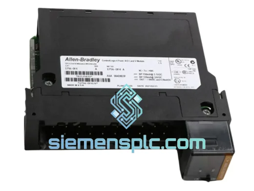
Allen-Bradley 1756-OF4 PLC Analog Output Module
ControlLogix
Origin US
PLC Analog Output Module
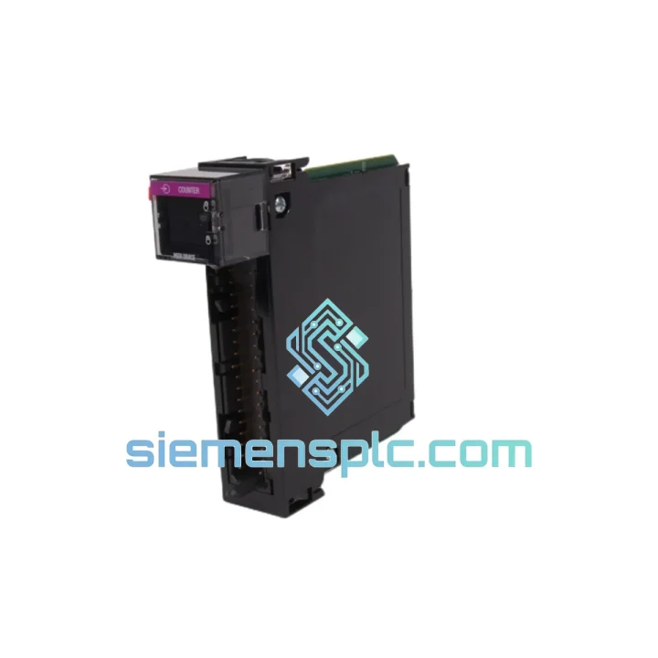
Request verified availability, condition, replacement risk review, packing options and courier lead time for 1756-LSC8XIB8I.
Click Request Quote and the part number is inserted into the inquiry form automatically.
Core fields for model confirmation and RFQ routing. Detailed product narrative remains below.
In precision-driven industrial environments — bottling lines running at 600 units/min, CNC machining centers holding ±2 µm tolerances, or custody-transfer flow stations governed by API MPMS Chapter 21.1 — the integrity of pulse data from encoders, proximity sensors, and turbine meters is non-negotiable. Standard digital input modules, constrained by firmware polling cycles of 2–10 ms, introduce latency that translates directly into positional error, count loss, and audit failures. At 500 kHz encoder output, a single 2 ms polling gap represents 1,000 unprocessed pulses — an unacceptable condition in any closed-loop or metering application.
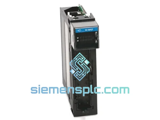
The Allen-Bradley 1756-LSC8XIB8I addresses this constraint at the silicon level. It is a dedicated ControlLogix counter input module providing eight fully isolated, independently configurable counter channels, each capable of processing pulse trains up to 1 MHz. Counting logic executes within the module’s onboard ASIC, operating asynchronously from the controller scan cycle. The ControlLogix backplane delivers timestamped count registers to the CPU every scan, with no dependency on firmware polling. The hardware latch input per channel captures encoder position with sub-microsecond latency — a deterministic, silicon-level event that remains unaffected by controller load or task period.
This architecture makes the 1756-LSC8XIB8I the correct selection for any application where pulse fidelity, channel isolation, and multi-axis simultaneous acquisition are required within a single ControlLogix chassis slot.
📦 Real-time Stock & RFQ: [email protected] | WhatsApp: +86 18359268345
| Part Number | 1756-LSC8XIB8I |
| Series | ControlLogix 1756 |
| Manufacturer | Allen-Bradley / Rockwell Automation |
| Counter Channels | 8, fully isolated channel-to-channel |
| Maximum Input Frequency | 1 MHz per channel |
| Counter Modes | Pulse, Quadrature (×1, ×2, ×4), Period, Frequency, Gate |
| Input Voltage Range | 5–24 VDC (individually configurable per channel) |
| Channel Isolation | Channel-to-channel isolated; prevents ground loop interference |
| Hardware Latch Latency | <1 µs (silicon-level capture, independent of scan cycle) |
| Counter Register Width | 32-bit (max count: 4,294,967,295) |
| Internal Timebase | 80 MHz (used for period/frequency measurement accuracy) |
| Backplane Interface | ControlLogix 1756 backplane, any chassis slot |
| Backplane Power Draw | 325 mA @ 5 VDC |
| Operating Temperature | 0 to 60 °C (32 to 140 °F) |
| Storage Temperature | −40 to 85 °C |
| Relative Humidity | 5–95% non-condensing |
| Dimensions (H × W × D) | 94.0 × 44.5 × 99.1 mm (single-slot 1756 form factor) |
| Weight | Approx. 200 g |
| Certifications | UL 508, CE (EN 61131-2), C-Tick/RCM, ATEX Zone 2 (with certified enclosure), RoHS |
| Programming Environment | Studio 5000 Logix Designer v21.00 or later |
| Add-On Profile (AOP) | Available via Rockwell Automation PCDC |
| Warranty | 12 months from date of shipment |
The 1756-LSC8XIB8I is built around a dedicated counting ASIC rather than a general-purpose microcontroller. This distinction is architecturally significant: the ASIC implements counting logic in combinational and sequential hardware, not firmware loops. Each of the eight channels maintains its own 32-bit accumulator, clocked directly from the incoming pulse train or quadrature signal. The 80 MHz internal timebase provides the reference for period and frequency measurement, yielding a frequency resolution of 12.5 ns per period count — sufficient for ±0.01% accuracy at 5 kHz turbine meter outputs.
Channel-to-Channel Isolation: Each input channel is galvanically isolated from adjacent channels and from the backplane logic supply. This isolation topology eliminates common-mode noise coupling between encoder signal lines routed through the same cable tray — a frequent source of phantom counts in multi-axis systems where motor drive cables and encoder cables share conduit. The isolation barrier is rated to withstand transient overvoltages consistent with IEC 61000-4-5 Level 3 surge immunity testing.
Quadrature Decoding Logic: In quadrature ×4 mode, the ASIC evaluates both rising and falling edges of both the A and B channels, producing four count events per encoder cycle. For a 1024 PPR encoder, this yields 4,096 effective counts per revolution — resolving angular position to 0.088° without any software interpolation. The Z-index (marker pulse) is captured via the hardware latch input, resetting or loading the counter register within <1 µs of the index event, independent of the controller scan period.
EMC Design: The module’s PCB layout routes high-frequency counter input traces with controlled impedance and ground plane shielding between signal layers. Ferrite bead filtering on each input line attenuates common-mode noise above 10 MHz, consistent with EN 55011 Class A industrial emission limits. The backplane connector uses a low-inductance ground return path, minimizing backplane-coupled noise during high-dV/dt switching events from adjacent drive modules.
Latch Input Architecture: The hardware latch input on each channel connects directly to a flip-flop within the ASIC, bypassing all firmware paths. When the latch signal transitions, the current counter register value is captured into a shadow register in the same clock cycle as the ASIC’s internal clock — approximately 12.5 ns resolution. This captured value is then transferred to the backplane data register and is available to the controller at the next scan boundary. The result is a latch latency of <1 µs end-to-end, making the module suitable for flying cutoff, registration mark detection, and die-bond position capture at sub-micron resolution.
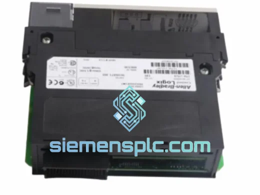
Every 1756-LSC8XIB8I unit offered through siemensplc.com undergoes a structured four-stage verification process before dispatch. Visual inspection confirms housing integrity, label authenticity, firmware revision sticker, and connector pin condition against factory reference specifications — counterfeit indicators including label adhesive, font geometry, and logo registration are examined under magnification. Functional bench testing installs the module in a live 1756 chassis running Studio 5000; all eight counter channels are exercised with a calibrated pulse generator at both 100 kHz and 1 MHz, and latch inputs are verified with a sub-microsecond trigger signal. Firmware revision is confirmed against the Rockwell Automation PCDC compatibility matrix for Studio 5000 v21 through v36. Final packaging uses anti-static bags with desiccant packs, foam-lined cartons, and shock indicators — protecting the module through international transit.
Shipments originate from Xiamen, China, via DHL Express, FedEx International Priority, and UPS Worldwide Expedited. Standard transit time to major industrial hubs — Frankfurt, Chicago, Singapore, Dubai, São Paulo — is 3 to 5 business days. Full export documentation is included with every shipment: commercial invoice, packing list, certificate of origin, ECCN classification (EAR99 for most destinations), and HTS code. A certificate of conformance and functional test report are available upon request. The 12-month warranty covers verified manufacturing defects; advance replacement units are available for critical production environments subject to prior arrangement.
Email: [email protected]
WhatsApp: +86 18359268345
Web: siemensplc.com
Location: Xiamen, China
© 2026 siemensplc.com. All rights reserved.
We check the full part number, brand, series and visible nameplate information before quotation.
Sales confirms stock path, condition option, quantity and realistic lead time for export dispatch.
DHL, FedEx, UPS or buyer courier arrangements can be reviewed with packing requirements.
Similar brand or category products for fast comparison and multi-item RFQ lists.