Mitsubishi Electric
RFQ Ready
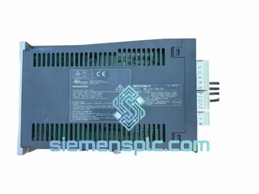
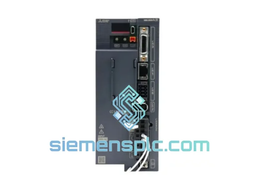
Mitsubishi MR-JE-70C AC Servo Amplifier
MELSERVO-JE CC-Link IE
Origin JP
AC Servo Amplifier
Request verified availability, condition, replacement risk review, packing options and courier lead time for A54GA5.5B BC186A437G52.
Click Request Quote and the part number is inserted into the inquiry form automatically.
Core fields for model confirmation and RFQ routing. Detailed product narrative remains below.
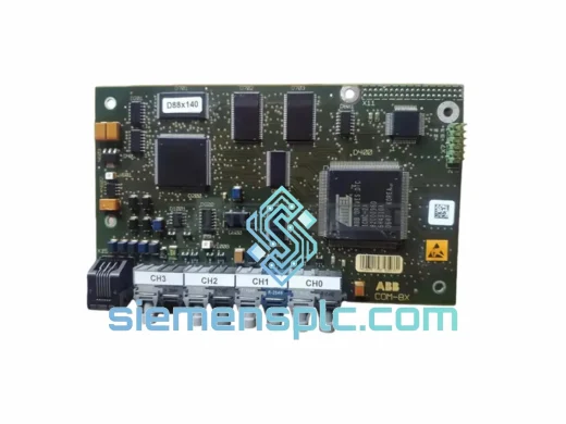
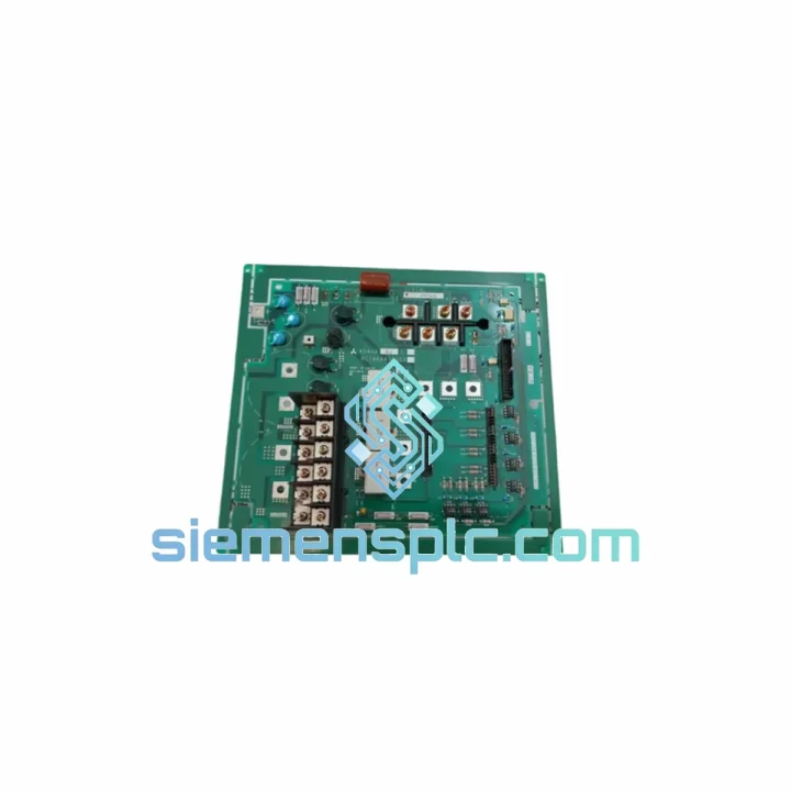
The Mitsubishi Electric A54GA5.5B BC186A437G52 is a factory-original power drive board engineered for deployment within Mitsubishi’s A-Series servo and inverter drive platforms. Rated at the 5.5 kW power class, this PCB occupies the critical interface layer between the control logic stage and the IGBT power module, governing gate-drive signal conditioning, DC bus voltage sensing, and fault-state latch logic. Its board reference code BC186A437G52 identifies a specific PCB revision with defined copper trace geometry, component tolerances, and firmware handshake parameters — substitution with adjacent revisions (G51, G53) requires verified cross-referencing against drive chassis firmware version and hardware revision level.
In a typical A-Series drive topology, the drive board receives PWM command signals from the main control card via an isolated backplane connector. It then amplifies and level-shifts those signals through gate-driver ICs to switch the IGBT bridge at frequencies typically ranging from 2 kHz to 15 kHz, depending on the configured carrier frequency. The A54GA5.5B variant is calibrated for the 5.5 kW output class, meaning its current-sense shunt resistors, bootstrap capacitor sizing, and thermal derating curves are matched to the thermal envelope of a 5.5 kW IGBT module. Installing a board from a different power class — even within the same revision family — risks incorrect overcurrent trip thresholds and potential IGBT failure under load transients.
The BC186A437G52 board incorporates optocoupler-based galvanic isolation on all gate-drive output channels. Each IGBT gate signal passes through a dedicated high-speed optocoupler (typical propagation delay ≤ 1 µs), ensuring that the low-voltage control domain remains fully isolated from the high-voltage DC bus (typically 300–600 VDC depending on input supply class). This isolation architecture is essential for personnel safety and for preventing common-mode noise on the DC bus from corrupting PWM timing at the control card level.
Real-time Stock & RFQ: [email protected] | WhatsApp: +86 18359268345
| Part Number | A54GA5.5B |
| Board Reference Code | BC186A437G52 |
| Manufacturer | Mitsubishi Electric Corporation |
| Series | Mitsubishi A-Series Inverter / Servo Drive |
| Component Classification | Power Drive PCB / Gate-Drive Interface Board |
| Applicable Power Class | 5.5 kW |
| DC Bus Voltage Range | 200V class: 270–400 VDC / 400V class: 540–800 VDC (chassis-dependent) |
| Gate-Drive Isolation Method | Optocoupler galvanic isolation per IGBT channel |
| Typical Gate Signal Propagation Delay | ≤ 1 µs |
| PWM Carrier Frequency Range | 2 kHz – 15 kHz (drive parameter-dependent) |
| Control Interface | Isolated backplane connector to main control card |
| Fault Output | Hardware fault latch with drive-level alarm relay output |
| PCB Dimensions | Chassis-specific; refer to A-Series drive service manual |
| Operating Temperature | -10°C to +50°C (ambient, with forced-air cooling) |
| Storage Temperature | -20°C to +65°C |
| Humidity | 5% – 95% RH, non-condensing |
| Weight (approx.) | 400 g |
| Country of Origin | Japan |
| Warranty | 12 months from date of shipment |
The A54GA5.5B BC186A437G52 board’s hardware architecture reflects Mitsubishi Electric’s design discipline for industrial-grade power electronics. Several aspects merit detailed examination:
Gate-Drive Bootstrap Circuit Design: The upper-side IGBT gate drivers in a half-bridge topology require a floating power supply referenced to the emitter of the upper switch. The A54GA5.5B achieves this via bootstrap capacitors charged during the lower-switch conduction interval. The capacitor sizing is matched to the 5.5 kW IGBT module’s gate charge (Qg) specification, ensuring sufficient gate voltage (typically +15 V / -8 V) is maintained across the full PWM duty cycle range without bootstrap capacitor droop at low modulation indices.
EMC Design and Common-Mode Noise Suppression: The PCB layout employs a split ground plane strategy: the low-voltage signal ground (SGND) and the gate-drive return (PGND) are connected at a single star point, preventing high-frequency switching currents from the IGBT gate loops from injecting noise into the analog sensing circuits. Ferrite bead filters are placed on gate-drive output traces to suppress high-frequency ringing caused by IGBT parasitic inductance during switching transitions. This approach reduces radiated EMI and protects the current-sense amplifier inputs from saturation during hard-switching events.
DC Bus Voltage Sensing and Overvoltage Protection: A resistive voltage divider network on the board samples the DC bus voltage and feeds it to a comparator circuit. If the bus voltage exceeds the overvoltage threshold (typically 115–120% of rated DC bus), the comparator output immediately asserts a hardware fault signal that disables all gate-drive outputs within one PWM cycle — a response time far faster than any software-based protection loop. This hardware-level protection is independent of the main control card, providing a fail-safe layer against regenerative overvoltage events during motor deceleration.
Thermal Derating and NTC Thermistor Interface: The board includes an NTC thermistor interface circuit that reads the IGBT module case temperature. The thermistor signal is conditioned by a linearization network and fed to the drive’s thermal management firmware. If the IGBT case temperature approaches the derating threshold (typically 80–90°C), the drive firmware reduces the PWM carrier frequency to lower switching losses, extending IGBT service life without requiring a full fault trip.
Fault Latch Logic: Hardware fault conditions (overcurrent, overvoltage, gate-drive undervoltage) are latched by a dedicated SR flip-flop circuit on the board. Once latched, the fault state persists until a deliberate reset signal is received from the control card — preventing automatic restart after a destructive fault event. This design choice aligns with IEC 61800-5-2 functional safety requirements for drive systems in industrial machinery.
Every Mitsubishi A54GA5.5B BC186A437G52 unit dispatched from our Xiamen, China facility undergoes a structured pre-shipment verification process. Boards are powered up on a dedicated test fixture that replicates the A-Series drive backplane interface, verifying gate-drive output voltages, fault latch behavior, and optocoupler response time before packaging. Units sourced from authorized distribution channels carry full lot traceability documentation, including manufacturer date codes and batch certificates.
Packaging follows anti-static and moisture-control protocols: each board is sealed in an ESD-protective bag with desiccant, placed in foam-lined rigid packaging rated for international air freight handling. Shipment from Xiamen is available via DHL Express, FedEx International Priority, and UPS Worldwide Expedited, with typical transit times of 3–7 business days to major industrial hubs in Europe, North America, Southeast Asia, and the Middle East. Export documentation — including commercial invoice, packing list, and certificate of origin — is prepared in compliance with customs requirements for the destination country. HS code classification is provided for smooth customs clearance.
A 12-month warranty covers manufacturing defects and verified functional failures under normal operating conditions. Warranty claims are processed with a defined RMA procedure: the defective unit is returned to Xiamen for inspection, and a replacement or repaired unit is dispatched within 5 business days of receipt. For mission-critical applications requiring zero downtime, advance replacement arrangements can be discussed at the time of order.
Email: [email protected]
WhatsApp: +86 18359268345
Web: siemensplc.com
Location: Xiamen, China
© 2026 siemensplc.com. All rights reserved.
We check the full part number, brand, series and visible nameplate information before quotation.
Sales confirms stock path, condition option, quantity and realistic lead time for export dispatch.
DHL, FedEx, UPS or buyer courier arrangements can be reviewed with packing requirements.
Similar brand or category products for fast comparison and multi-item RFQ lists.