AI-Tek
In Stock OK
AI-Tek 70084-1713-111 Speed Sensor – 70084 Series
Request verified availability, condition, replacement risk review, packing options and courier lead time for 70084-1713-111.
BrandAI-Tek
Part Number70084-1713-111
ConditionAvailability Check
Lead TimeRFQ Confirmation
DocumentsDatasheet / photos by RFQ
ShippingExport packing available
Auto-filled RFQ
70084-1713-111
Click Request Quote and the part number is inserted into the inquiry form automatically.
- Reply by email: [email protected]
- WhatsApp / Tel: +86 18359268345
- Mon-Sat 9:00-18:00 GMT+8
Procurement Data
Key Product Information
Core fields for model confirmation and RFQ routing. Detailed product narrative remains below.
- Brand
- AI-Tek
- Primary Part Number
- 70084-1713-111
- Product Type
- Speed Sensor
- Product Family
- Other series
- Manufacturer
- AI-Tek Instruments
- Country of Origin
- United States
- Catalog Category
- Sensors & Switches
- Operating Temp.
- Consult datasheet; typical VR range –55 °C to +150 °C
- Warranty
- 12 months from date of dispatch
Model confirmed for inquiry
70084-1713-111
Send quantity, destination and urgency. The RFQ form keeps this part number attached.
Request Quote
Product Overview
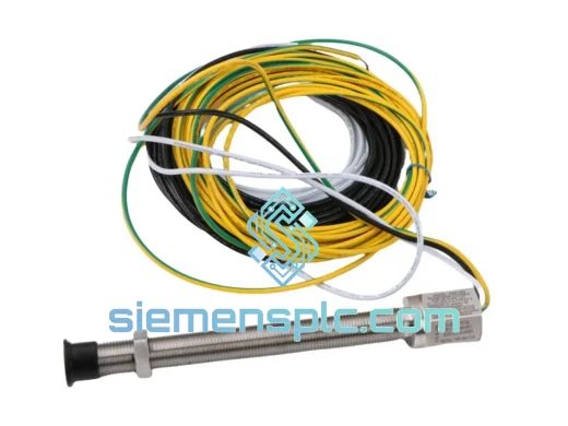
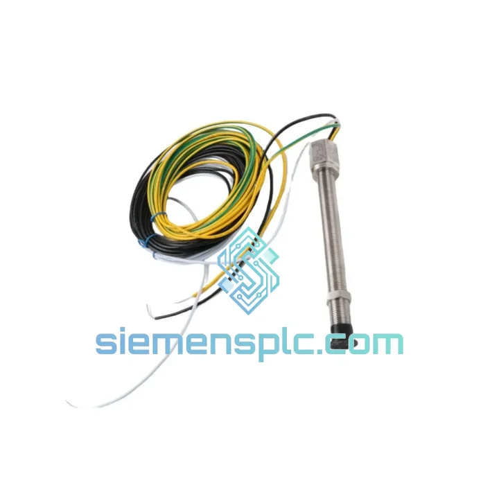
AI-Tek 70084-1713-111 Variable Reluctance Magnetic Pickup — Passive Speed Sensing in Closed-Loop Industrial Control
The AI-Tek 70084-1713-111 is a passive variable reluctance (VR) magnetic pickup sensor designed for continuous rotational speed measurement in industrial drive systems, turbomachinery, and process automation loops. Unlike active Hall-effect or proximity-type sensors, the 70084-1713-111 requires no external excitation voltage. Signal generation is entirely self-powered through electromagnetic induction: as each ferromagnetic gear tooth passes the sensor’s pole piece, the change in magnetic flux induces a sinusoidal AC voltage across the coil winding. Amplitude scales proportionally with shaft speed and gear-tooth geometry, providing a direct, analog-faithful representation of rotational velocity to the receiving controller.
The -111 suffix designates the cable assembly variant within the 70084 platform, specifying a factory-terminated lead configuration suited for direct field termination to PLC high-speed counter (HSC) input cards, DCS speed-input modules, or dedicated frequency-to-voltage signal conditioners. The 3/4-20 UNF threaded body allows precise air-gap adjustment via jam-nut locking, a critical installation parameter for maintaining signal amplitude within the input threshold window of downstream electronics.
Deployment environments for the 70084-1713-111 span electric motor closed-loop feedback systems, conveyor belt slip detection, gas and steam turbine shaft monitoring, centrifugal compressor speed control, gearbox condition monitoring, and paper machine web-tension control. In each application, the sensor’s passive architecture eliminates a failure mode present in active sensors: loss of supply voltage does not produce a false zero-speed signal — the output simply ceases, a behavior that safety-rated speed monitoring circuits can distinguish from a genuine standstill condition when paired with an appropriate safety relay module.
The 70084 series has accumulated decades of field deployment across power generation, heavy process industry, and OEM machine builder applications. The 70084-1713-111 variant is stocked and dispatched from Xiamen, China, with full export documentation available for international procurement.
Real-time Stock & RFQ: [email protected] | WhatsApp: +86 18359268345
Technical Parameters
| Parameter | Value / Specification |
|---|---|
| Part Number | 70084-1713-111 |
| Manufacturer | AI-Tek Instruments |
| Series | 70084 |
| Sensor Technology | Passive Variable Reluctance (VR) / Electromagnetic Induction |
| Output Signal Type | Sinusoidal AC voltage |
| Output Amplitude | Proportional to shaft speed and gear-tooth geometry |
| External Power Required | None (self-generating passive sensor) |
| Thread Size | 3/4-20 UNF |
| Cable Variant Suffix | -111 (factory-terminated lead assembly) |
| Target Wheel Material | Ferromagnetic steel (required) |
| Recommended Air Gap | 0.25 mm – 1.50 mm (tip-to-tooth) |
| Operating Temperature | Consult datasheet; typical VR range –55 °C to +150 °C |
| Weight | 350 g |
| Mounting | Threaded body with jam-nut locking |
| PLC/DCS Compatibility | HSC input cards, frequency-to-voltage converters, tachometer modules |
| Warranty | 12 months from date of dispatch |
| Country of Origin | United States |
Hardware Logical Analysis
Electromagnetic Induction Architecture: The 70084-1713-111 operates on Faraday’s law of electromagnetic induction. A permanent magnet within the sensor body establishes a static magnetic field through the pole piece. When a ferromagnetic gear tooth enters the field, reluctance in the magnetic circuit decreases, increasing flux density. As the tooth exits, reluctance rises and flux density falls. This cyclic flux change induces a voltage in the coil winding: V = –N × dΦ/dt, where N is the coil turn count and dΦ/dt is the rate of flux change. The result is a sinusoidal output whose frequency equals the product of shaft RPM and gear-tooth count, and whose amplitude increases with shaft speed.
EMC and Noise Immunity: The passive coil architecture provides inherent immunity to conducted electrical noise on the supply rail — there is no supply rail. Common-mode interference rejection is achieved through the differential nature of the coil output: shielded twisted-pair cabling (e.g., Belden 9501 or equivalent) routes the differential signal to the receiver, with the shield grounded at one end only to prevent ground-loop currents. The sensor’s high source impedance at low speeds requires that the receiving input card present a sufficiently high input impedance (typically ≥10 kΩ) to avoid signal loading and amplitude attenuation.
Air Gap Sensitivity and Signal Integrity: The 0.25 mm to 1.50 mm recommended air gap is not arbitrary. Below 0.25 mm, mechanical runout on the target wheel risks physical contact with the sensor tip, causing catastrophic damage. Above 1.50 mm, the rate of flux change (dΦ/dt) at low shaft speeds may fall below the minimum input threshold of the receiving electronics, producing missed pulses and erroneous speed readings. The 3/4-20 UNF thread pitch (1.27 mm/turn) allows sub-millimeter air gap adjustment with a single partial turn, enabling precise field calibration without specialized tooling.
Passive Fail-State Behavior: In safety-instrumented systems (SIS), the passive sensor’s fail-state behavior is deterministic: a broken coil or open-circuit cable produces a zero-amplitude output, distinguishable from a genuine zero-speed condition by the absence of any signal rather than a sustained DC level. When interfaced with a safety relay module (e.g., Pilz PNOZ or Siemens 3TK28 series) configured for under-speed detection, this characteristic supports SIL 2 speed monitoring architectures per IEC 62061.
System Integration Benefits
- Zero-power sensing node: No 24 VDC supply wiring to the sensor head reduces panel wiring complexity, eliminates a power-supply single point of failure at the field device level, and simplifies ATEX/IECEx zone wiring calculations in hazardous-area installations.
- Direct HSC input compatibility: The sinusoidal output is accepted natively by Siemens S7-1200/1500 HSC input modules, Allen-Bradley 1756-HSC cards, and Schneider Modicon HSC modules without signal conditioning, reducing BOM cost and latency in the speed feedback path.
- Deterministic frequency output: Frequency = RPM × tooth count / 60. This linear relationship allows the PLC to compute shaft speed with a single division operation per scan cycle, imposing negligible CPU load even at high tooth-count resolutions (e.g., 60-tooth wheel at 3000 RPM = 3000 Hz input frequency).
- Wide dynamic speed range: The VR sensor’s output frequency tracks shaft speed from near-zero RPM (limited by minimum dΦ/dt threshold) to high-speed applications exceeding 10,000 RPM, without sensor swap-out or range switching — a single device covers startup, normal operation, and over-speed detection.
- Mechanical robustness at the sensing head: No active electronics, no LED emitters, no optical windows, and no Hall-effect ICs in the sensing tip. The sensor head contains only a permanent magnet, pole piece, and coil winding — components with no wear mechanisms and no sensitivity to oil mist, coolant splash, or moderate vibration levels typical of gearbox housings.
- Diagnostic transparency via amplitude monitoring: Because output amplitude is proportional to speed, a sudden amplitude drop at constant RPM indicates increasing air gap (mechanical wear or mounting shift) before signal loss occurs. Controllers with analog speed-input cards can monitor amplitude as a secondary diagnostic channel for predictive maintenance.
- Safety architecture compatibility: The passive fail-state (open-circuit = zero output) is compatible with under-speed safety relay logic, supporting SIL 2 speed monitoring loops per IEC 62061 and PLd/Cat. 3 architectures per ISO 13849-1 when combined with appropriate safety relay modules.
- Standardized mechanical interface: The 3/4-20 UNF thread is the AI-Tek 70084 platform standard, ensuring backward compatibility with existing mounting brackets, conduit fittings, and jam-nut hardware across the installed base — no re-engineering of mechanical interfaces when replacing legacy sensors.
Quality Assurance & Global Logistics
Every AI-Tek 70084-1713-111 unit dispatched from our Xiamen, China facility is sourced through verified industrial distribution channels carrying authentic AI-Tek Instruments documentation. Pre-shipment inspection covers part number label verification against manufacturer documentation, coil continuity check, visual inspection of thread integrity and cable termination, and anti-static packaging for electrostatic-sensitive coil assemblies.
Export documentation — commercial invoice, packing list, certificate of origin, and HS code declaration (HS 8543.70 or applicable subheading) — is prepared for every international shipment. DHL Express, FedEx International Priority, and sea-freight consolidation options are available depending on order volume and urgency. Typical dispatch lead time for in-stock units is 1–3 business days from order confirmation. A 12-month warranty covers manufacturing defects; warranty claims are processed with replacement dispatch from Xiamen within 5 business days of confirmed fault diagnosis.
For bulk procurement (>10 units), project-based blanket orders, or expedited sourcing for plant shutdowns, contact the sales team directly for priority allocation and formal quotation.
Contact Information
Email: [email protected]
WhatsApp: +86 18359268345
Web: siemensplc.com
Location: Xiamen, China
© 2026 siemensplc.com. All rights reserved.
Ready to quote
[email protected]
Send This Part Number to Sales
RFQ workflow
Quality workflow ->
Confirmation Process
01Model confirmation
We check the full part number, brand, series and visible nameplate information before quotation.
02Availability reply
Sales confirms stock path, condition option, quantity and realistic lead time for export dispatch.
03Packing & courier
DHL, FedEx, UPS or buyer courier arrangements can be reviewed with packing requirements.
Continue sourcing
Browse full catalog ->
Related Automation Parts
Similar brand or category products for fast comparison and multi-item RFQ lists.
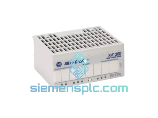
Allen-Bradley
RFQ Ready
Allen-Bradley 1440-TPR06-00RE Absolute Position Transducer
Rockwell Automation
Origin US
Absolute Position Transducer
ABB
RFQ Ready
ABB SPAU130C-AA Voltage Protection Relay
SPAU 130 Series
Origin SE
Voltage Protection Relay