Woodward
RFQ Ready
WOODWARD 9907-345 Overspeed Protection System – EG Series
EG Series
Origin US
Overspeed Protection System
Request verified availability, condition, replacement risk review, packing options and courier lead time for 8440-2152.
Click Request Quote and the part number is inserted into the inquiry form automatically.
Core fields for model confirmation and RFQ routing. Detailed product narrative remains below.
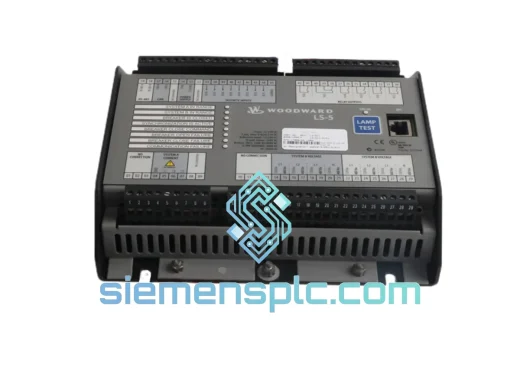
The Woodward 8440-2152 is a dedicated circuit breaker relay output module within the LS-5 V2 distributed control platform, engineered for turbine governor and generator protection systems where deterministic switching latency and contact integrity are non-negotiable. Operating as a discrete output node on the LS-5 V2 relay bus backplane, this module interfaces directly with the LS-5 V2 CPU via a proprietary 24 VDC serial relay bus, executing trip and permissive commands with sub-10 ms end-to-end response from logic assertion to dry-contact closure. Each relay channel is individually addressable, allowing the CPU to assert, de-assert, and read-back contact state without shared-bus arbitration conflicts — a design that eliminates the race conditions common in multiplexed relay architectures.
In a typical gas turbine control loop, the 8440-2152 sits between the governor CPU output stage and the fuel valve solenoid or breaker coil. When the CPU evaluates a trip condition — overspeed, loss of flame, or differential pressure exceedance — the relay command propagates across the backplane bus and the 8440-2152 opens or closes the designated contact within a single bus scan cycle. This deterministic behavior is critical in SIL-rated safety loops where response time directly affects the probability of dangerous failure on demand (PFDavg).
Real-time Stock & RFQ: [email protected] | WhatsApp: +86 18359268345
| Parameter | Specification |
|---|---|
| Part Number | 8440-2152 |
| Series / Platform | Woodward LS-5 V2 |
| Module Function | Circuit Breaker Relay Output Module |
| Relay Bus Voltage | 24 VDC nominal (18–32 VDC operating range) |
| Number of Relay Channels | 8 independent Form-C (SPDT) relay outputs |
| Contact Rating (Resistive) | 5 A @ 250 VAC / 5 A @ 30 VDC |
| Contact Rating (Inductive) | 2 A @ 250 VAC (cos φ = 0.4) |
| Relay Operate Time | ≤ 8 ms (coil energize to contact closure) |
| Relay Release Time | ≤ 5 ms |
| Electrical Isolation | 2,500 VAC (coil-to-contact, 1 min dielectric) |
| Backplane Bus Interface | Woodward LS-5 V2 proprietary relay bus (35-pin DIN connector) |
| Operating Temperature | -40 °C to +70 °C |
| Storage Temperature | -55 °C to +85 °C |
| Relative Humidity | 5–95% RH, non-condensing |
| Vibration Resistance | IEC 60068-2-6: 5–150 Hz, 1 g |
| Shock Resistance | IEC 60068-2-27: 15 g, 11 ms half-sine |
| EMC Immunity | IEC 61000-4-2/3/4/5/6 (ESD, RF, EFT, Surge, Conducted) |
| Enclosure / Form Factor | Plug-in module, LS-5 V2 chassis slot (no DIN-rail standalone) |
| Weight | 380 g (approx.) |
| Certifications | CE, UL 508 (industrial control equipment) |
| Warranty | 12 months from date of shipment |
The 8440-2152 implements a relay bus slave architecture where each of its eight relay channels is mapped to a unique bus address register maintained by the LS-5 V2 CPU. The backplane communication protocol uses a polled master-slave scheme: the CPU asserts a channel address and command byte on the bus, and the 8440-2152 latches the command into a local relay driver register within one bus clock cycle (typically 1 ms). This eliminates the need for handshake acknowledgment loops that would otherwise add variable latency to safety-critical switching events.
From an EMC standpoint, the module employs a two-stage transient suppression architecture on each relay coil driver: a flyback diode clamps inductive kickback from the relay coil to within 1.5× supply voltage, while a secondary TVS diode on the bus interface line absorbs conducted transients up to 600 W peak (10/1000 µs waveform per IEC 61000-4-5). The contact output terminals are routed through a common-mode choke before reaching the terminal block, attenuating high-frequency noise coupled from adjacent power wiring — a design consideration particularly relevant in switchgear panels where 480 VAC bus bars run in close proximity to control wiring.
The relay coil drivers are implemented with solid-state MOSFET switches rather than bipolar transistors, providing lower on-resistance (RDS(on) < 0.5 Ω) and eliminating the thermal runaway risk associated with BJT-based drivers in high-ambient-temperature turbine enclosures. Each driver channel includes an open-load detection circuit: if the relay coil circuit is broken (connector pull-out, coil failure), the driver detects the absence of coil current and flags a diagnostic fault to the CPU via the bus status register, enabling the control system to annunciate a maintenance alarm before the fault propagates to a process trip.
Contact arc suppression is handled by RC snubber networks (typically 100 Ω / 0.1 µF) across each Form-C contact pair, extending contact life when switching inductive loads such as solenoid valves and motor starters. This is particularly significant in applications where relay cycle counts exceed 100,000 operations per year — a common occurrence in compressor anti-surge control loops.
Every Woodward 8440-2152 unit supplied by siemensplc.com is sourced through verified industrial distribution channels and subjected to a structured incoming inspection protocol before entering our Xiamen warehouse. Inspection covers label authenticity verification (hologram, date code, lot traceability), housing integrity assessment, connector pin alignment check, and where test fixtures are available, a functional power-on verification against known-good reference units.
All units are stored in a temperature-controlled, ESD-protected warehouse environment (20–25 °C, <60% RH, ESD flooring and wrist-strap stations at all handling points). Outbound packaging uses anti-static PE foam inserts within double-wall corrugated cartons, with desiccant packs included for ocean freight shipments. Each shipment is accompanied by a commercial invoice, packing list, and HS code documentation (HS 8536.49 for relay modules) to facilitate smooth customs clearance in the EU, US, Southeast Asia, and Middle East markets.
Standard lead time for in-stock units is 3–5 business days door-to-door via DHL Express or FedEx International Priority from Xiamen, China. For bulk orders or sourced units, lead time is 10–21 business days. A 12-month warranty covers manufacturing defects and premature failure under normal operating conditions. Warranty claims are processed with a replacement-first policy to minimize customer downtime.
📧 Email: [email protected]
📱 WhatsApp: +86 18359268345
🌐 Web: siemensplc.com
📍 Location: Xiamen, China
© 2026 siemensplc.com. All rights reserved.
We check the full part number, brand, series and visible nameplate information before quotation.
Sales confirms stock path, condition option, quantity and realistic lead time for export dispatch.
DHL, FedEx, UPS or buyer courier arrangements can be reviewed with packing requirements.
Similar brand or category products for fast comparison and multi-item RFQ lists.