Yokogawa
RFQ Ready
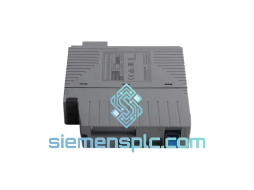
YOKOGAWA EB401-10 DCS Interface Module – CENTUM VP / CS 3000
CENTUM VP
Origin JP
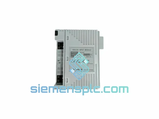
DCS Interface Module
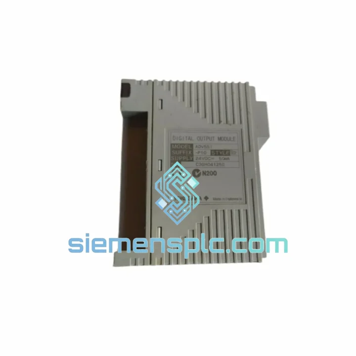
Request verified availability, condition, replacement risk review, packing options and courier lead time for ADV551-P10.
Click Request Quote and the part number is inserted into the inquiry form automatically.
Core fields for model confirmation and RFQ routing. Detailed product narrative remains below.
The ADV551-P10 occupies a well-defined position within YOKOGAWA’s CENTUM VP and CS 3000 distributed control system hierarchy. As a discrete output module installed directly into the I/O nest of a Field Control Station (FCS), it serves as the terminal interface between the deterministic control logic executed on the FCS processor and the physical actuators — solenoid valves, motor contactors, alarm annunciators, and interlock relays — that govern process behavior on the plant floor. Its role is not peripheral; in any loop where a binary command must be issued with sub-100 ms latency and confirmed by the FCS watchdog, the ADV551-P10 is the last hardware boundary before the field.
Unlike general-purpose PLC output cards that rely on software polling cycles, the ADV551-P10 communicates over YOKOGAWA’s proprietary V-net/IP or ESB (Enhanced Signal Bus) backplane, which enforces a fixed, deterministic scan cycle. This architectural choice eliminates jitter at the output stage — a critical requirement in interlock and emergency shutdown (ESD) applications where output state must be guaranteed within a defined time window. The module’s internal state machine continuously monitors the FCS heartbeat; if the heartbeat is lost, the module drives outputs to a pre-configured fail-safe state without waiting for a software command, a behavior that is hardwired into the module’s ASIC logic rather than implemented in firmware.
Real-time Stock & RFQ: [email protected] | WhatsApp: +86 18359268345
| Part Number | ADV551-P10 |
| Manufacturer | YOKOGAWA Electric Corporation |
| Module Classification | Digital Output (DO) Module — Transistor Type |
| Compatible Platform | CENTUM VP, CENTUM CS 3000 (FCS / KFCS / LFCS) |
| Output Channels | 16 points, individually addressable |
| Output Device Type | NPN open-collector transistor |
| Rated Load Voltage | 24 VDC (field side, externally supplied) |
| Maximum Load Current per Channel | 0.1 A (100 mA) |
| Total Module Load Current | 1.6 A maximum (all channels ON simultaneously) |
| ON-State Voltage Drop | ≤ 1.5 V at rated current |
| OFF-State Leakage Current | ≤ 0.1 mA |
| Isolation Method | Photocoupler (optical isolation), field side vs. system bus |
| Isolation Voltage | 500 VAC rms, 1 minute (field to system bus) |
| Response Time (OFF→ON) | ≤ 1 ms |
| Response Time (ON→OFF) | ≤ 1 ms |
| Internal Power Consumption | Supplied via I/O nest backplane (5 VDC system bus) |
| Operating Temperature | 0°C to +60°C |
| Storage Temperature | −25°C to +70°C |
| Relative Humidity | 5% to 95% RH, non-condensing |
| Mounting | CENTUM VP / CS 3000 I/O nest (nest-mount, hot-swap capable) |
| Dimensions (W × H × D) | Approx. 28.5 × 100 × 83 mm (single nest slot) |
| Weight | Approx. 200 g |
| Certifications | CE Marking, UL Listed (verify current revision against project datasheet) |
| Warranty | 12 months from date of shipment — genuine YOKOGAWA hardware |
Photocoupler Isolation Architecture
Each of the 16 output channels is driven through an individual photocoupler. The LED side of the coupler is driven by the module’s internal logic (system bus domain, 5 VDC), while the phototransistor side interfaces directly with the field wiring (24 VDC domain). This arrangement creates a galvanic barrier with a withstand voltage of 500 VAC rms, preventing ground loops, common-mode transients, and inductive kickback from solenoid coils from propagating back into the FCS backplane. In environments with variable-frequency drives (VFDs) or large motor starters in proximity, this isolation margin is not a safety margin — it is an operational necessity.
NPN Open-Collector Output Stage
The transistor output stage uses an NPN open-collector topology. The collector of each output transistor is connected to the field terminal; the emitter is tied to the field-side common (0 VDC). When the FCS commands a channel ON, the transistor saturates, pulling the field terminal low and completing the load circuit through the externally supplied 24 VDC. This topology is inherently compatible with sourcing-type field devices and allows the field power supply to be isolated from the module’s internal supply — a standard requirement in IEC 61511 functional safety architectures.
Fail-Safe State Logic
The ADV551-P10 implements hardware-level fail-safe behavior. If the FCS processor fails to refresh the module’s output register within the watchdog timeout window (typically one scan cycle), the module’s internal logic de-energizes all outputs — driving them to the OFF (open-collector high-impedance) state. This behavior is implemented in the module’s gate array logic, not in the FCS application program, ensuring that the fail-safe response is independent of software execution state. For process applications where de-energize-to-trip (DTT) logic is used, this architecture directly supports SIL-rated interlock design.
EMC Design and Noise Immunity
The module’s PCB layout follows YOKOGAWA’s internal EMC design rules, which include ground plane partitioning between the system bus domain and the field I/O domain, ferrite bead filtering on field terminal lines, and transient voltage suppression (TVS) diodes on each output channel. The result is a module that meets IEC 61000-4-4 (EFT/Burst, 2 kV) and IEC 61000-4-5 (Surge, 1 kV) immunity levels — standard requirements for process industry installations where cable runs may exceed 100 meters and share conduit with power wiring.
Hot-Swap and Online Replacement
The ADV551-P10 supports online module replacement within a running CENTUM VP system, provided the FCS is configured for I/O module redundancy or the affected channels are placed in manual mode prior to extraction. The nest connector is rated for a defined number of insertion cycles, and the module’s internal initialization sequence — which includes self-test of the output driver stage and communication handshake with the FCS — completes within the FCS scan cycle, minimizing process disruption during maintenance.
Every ADV551-P10 unit supplied through siemensplc.com is sourced as genuine YOKOGAWA hardware — no remanufactured, relabeled, or counterfeit units are handled. Each module undergoes a structured incoming inspection protocol at our Xiamen facility that includes visual examination of the PCB, connector, and label integrity; verification of the module’s hardware revision marking against the order specification; and a functional power-on test confirming that the module’s self-diagnostic LED sequence completes without fault indication.
Xiamen’s geographic position — a major port city in Fujian Province with direct sea freight connections to Southeast Asia, the Middle East, Europe, and the Americas, and air freight access via Xiamen Gaoqi International Airport — enables competitive transit times to most industrial destinations. Standard air freight from Xiamen to Western Europe or the US East Coast typically clears customs within 5–8 business days. For plant shutdown scenarios requiring emergency delivery, DHL Express and FedEx Priority services from Xiamen can achieve 2–3 business day door-to-door transit to most major industrial hubs.
Export documentation — including commercial invoice, packing list, certificate of origin, and where required, CITES or dual-use export declarations — is prepared in-house by our logistics team. HS Code 8537.10 applies to this module category for most destination customs authorities. Customers in regulated industries (nuclear, defense, aerospace) should advise at the time of inquiry so that applicable export control screening can be completed prior to order confirmation.
All shipments are packed in anti-static ESD bags, placed in foam-lined cartons, and sealed with tamper-evident tape. For multi-unit orders, individual modules are separated by foam dividers to prevent mechanical contact during transit. A 12-month warranty from the date of shipment covers manufacturing defects and confirmed functional failures under normal operating conditions.
Email: [email protected]
WhatsApp: +86 18359268345
Web: siemensplc.com
Location: Xiamen, Fujian, China
© 2026 siemensplc.com. All rights reserved.
We check the full part number, brand, series and visible nameplate information before quotation.
Sales confirms stock path, condition option, quantity and realistic lead time for export dispatch.
DHL, FedEx, UPS or buyer courier arrangements can be reviewed with packing requirements.
Similar brand or category products for fast comparison and multi-item RFQ lists.