GE Fanuc
In Stock OK
GE IC693DSM314 Motion Controller – Series 90-30
Request verified availability, condition, replacement risk review, packing options and courier lead time for IC693DSM314.
BrandGE Fanuc
Part NumberIC693DSM314
ConditionAvailability Check
Lead TimeRFQ Confirmation
DocumentsDatasheet / photos by RFQ
ShippingExport packing available
Auto-filled RFQ
IC693DSM314
Click Request Quote and the part number is inserted into the inquiry form automatically.
- Reply by email: [email protected]
- WhatsApp / Tel: +86 18359268345
- Mon-Sat 9:00-18:00 GMT+8
Procurement Data
Key Product Information
Core fields for model confirmation and RFQ routing. Detailed product narrative remains below.
- Brand
- GE Fanuc
- Primary Part Number
- IC693DSM314
- Product Type
- Motion Controller
- Series / Family
- Fanuc
- Manufacturer
- GE Fanuc Automation
- Country of Origin
- US
- Catalog Category
- Robotics & Motion
- Operating Temp.
- 0 °C to +60 °C
- Warranty
- 12 months from date of shipment
Model confirmed for inquiry
IC693DSM314
Send quantity, destination and urgency. The RFQ form keeps this part number attached.
Request Quote
Product Overview
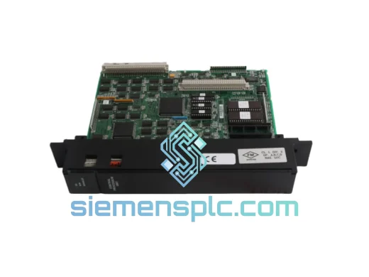
GE IC693DSM314 Motion Controller Module: Dedicated Axis Processing in Series 90-30 Control Architecture
The GE Fanuc IC693DSM314 is a dedicated Digital Servo Module (DSM) engineered for the Series 90-30 programmable logic controller platform. Unlike general-purpose I/O modules, the IC693DSM314 carries an onboard motion co-processor that executes position loop closure, velocity profiling, and torque command generation independently of the rack’s primary CPU. This architectural separation is not cosmetic — it eliminates the jitter introduced when motion calculations compete with ladder-logic scan cycles, delivering deterministic axis response times that general CPU-based motion cannot match.
In a typical Series 90-30 rack, the IC693DSM314 occupies a single I/O slot and communicates with the host CPU module via the 8-bit parallel backplane bus at a sustained throughput of approximately 1 MB/s. The module maintains its own servo loop at update rates independent of the PLC scan, allowing axis position error correction to occur at sub-millisecond intervals even when the CPU scan time extends due to complex logic processing. This decoupled execution model is the defining hardware advantage of the DSM architecture.
The module supports up to four axes of motion — configurable as stepper-pulse/direction outputs or analog ±10 V command signals for closed-loop servo drives. Each axis maintains independent position registers, following-error accumulators, and fault latch registers accessible to the host CPU via the backplane mailbox protocol. Axis state data is refreshed every scan, giving the PLC program full visibility into motion status without polling overhead.
Real-time Stock & RFQ: [email protected] | WhatsApp: +86 18359268345
Technical Parameters
| Parameter | Specification |
|---|---|
| Part Number | IC693DSM314 |
| Manufacturer | GE Fanuc Automation |
| Platform | Series 90-30 PLC |
| Module Category | Digital Servo / Motion Controller (DSM) |
| Axes Supported | Up to 4 axes (stepper or analog servo) |
| Stepper Output | Pulse/Direction, open-collector, 5 VDC logic |
| Analog Command Output | ±10 V DC, 12-bit resolution |
| Encoder Feedback Input | Quadrature incremental encoder, 5 VDC differential (RS-422) |
| Max Encoder Frequency | 250 kHz per axis |
| Backplane Interface | Series 90-30 parallel I/O bus |
| Backplane Power Draw | +5 VDC @ 1.5 A (typical) |
| Operating Temperature | 0 °C to +60 °C |
| Storage Temperature | −40 °C to +85 °C |
| Relative Humidity | 5 % to 95 % non-condensing |
| Form Factor | Single-slot Series 90-30 module |
| Approximate Weight | 340 g |
| Programming Environment | GE Proficy Machine Edition (Logic Developer – PLC) |
| Warranty | 12 months from date of shipment |
Hardware Logical Analysis
The IC693DSM314’s internal architecture centers on a dedicated motion co-processor — separate from the Series 90-30 CPU’s main processor — that runs the position control algorithm at a fixed servo update rate. This design choice has measurable consequences for system behavior:
Servo Loop Independence: The DSM’s position loop executes on its own clock domain. Even if the host CPU scan extends to 50 ms due to complex logic, the servo loop continues closing at its configured update rate. Following error does not accumulate during CPU-heavy scan cycles, which is a failure mode common in software-only motion implementations.
Backplane Mailbox Protocol: Communication between the IC693DSM314 and the CPU uses a structured mailbox mechanism over the Series 90-30 backplane. Command blocks (move type, target position, velocity, acceleration) are written by the CPU into the module’s input image table area. The DSM acknowledges execution status back through the output image table. This handshake protocol prevents partial command execution — a command is either fully accepted or rejected with a fault code, eliminating ambiguous mid-transfer states.
Encoder Interface Signal Conditioning: The quadrature encoder inputs on the IC693DSM314 use RS-422 differential line receivers. Differential signaling provides common-mode noise rejection of up to ±7 V, which is significant in industrial environments where encoder cables run parallel to motor power cables generating switching transients. The hardware quadrature decoder counts both edges of A and B channels (×4 multiplication), yielding effective position resolution four times the encoder’s mechanical line count without software overhead.
EMC Design Considerations: The module’s PCB layout isolates the analog command output circuitry from the digital backplane interface using a ground plane split. The ±10 V DAC output stage uses an instrumentation amplifier topology to maintain output accuracy in the presence of ground potential differences between the PLC rack and the servo drive chassis — a common source of offset error in single-ended analog command implementations.
Fault Latch Architecture: Each axis maintains a hardware fault latch register that captures the axis state at the moment a fault condition is detected (following error exceeded, encoder loss, drive fault input active). The latch preserves the pre-fault position count and velocity estimate, giving maintenance personnel precise diagnostic data without relying on software polling that might miss transient faults.
System Integration Benefits
- Deterministic Motion Execution: Servo loop closure occurs on the DSM’s own processor clock, decoupled from PLC scan variability. Axis position error correction latency is bounded regardless of CPU load, a prerequisite for coordinated multi-axis applications.
- Reduced CPU Scan Load: All trajectory interpolation, velocity ramping, and position error calculation execute on the DSM. The host CPU exchanges only high-level command and status data, freeing scan time for process logic, HMI communication, and network tasks.
- Transparent Diagnostic Visibility: Axis status registers — position, velocity estimate, following error, fault code — are mapped into the CPU’s I/O image table and updated every scan. No special function block polling is required; standard ladder contacts and coils can act directly on motion status bits.
- Scalable Multi-Axis Configuration: A single IC693DSM314 manages up to four axes. Multiple DSM modules can coexist in the same rack, allowing axis count to scale in four-axis increments without changing the CPU or rack hardware.
- Mixed Motion Mode Support: Individual axes can be configured independently as stepper (pulse/direction) or analog servo command outputs within the same module. This allows integration of both stepper-driven auxiliary axes and high-performance servo axes in a single motion subsystem.
- Standardized Programming Interface: Motion commands are issued through GE Proficy Machine Edition using standard DSM function blocks. The programming model is consistent across Series 90-30 CPU variants, reducing re-engineering effort when upgrading CPU modules.
- Hardware Following Error Protection: The DSM enforces a configurable following error limit in hardware. If the axis position error exceeds the threshold — indicating a drive fault, mechanical jam, or encoder failure — the module disables the command output and latches a fault code before the CPU scan can respond. This hardware-level protection reduces the risk of mechanical damage in high-speed applications.
- Backplane Hot-Swap Compatibility: The Series 90-30 platform supports module replacement procedures that minimize system downtime. The IC693DSM314’s configuration data is stored in the CPU’s program memory, allowing a replacement module to be initialized from the existing program without re-parameterization at the drive level.
Quality Assurance & Global Logistics
Every IC693DSM314 unit supplied by siemensplc.com is sourced through traceable industrial supply channels and subjected to a structured pre-shipment inspection protocol. Physical inspection covers PCB condition, connector pin integrity, label authenticity, and housing for evidence of rework or counterfeit markings. Where test fixtures are available, functional verification confirms backplane communication response and analog output calibration.
Units are packaged in anti-static bags with foam cushioning inside double-wall corrugated cartons rated for international air freight handling. Each shipment includes a commercial invoice, packing list, and certificate of origin. HS code documentation (typically 8537.10 for PLC modules) is prepared to support import clearance in major destination markets.
Logistics operations are based in Xiamen, China, with established carrier accounts for DHL Express, FedEx International Priority, and UPS Worldwide Express. In-stock units typically ship within 1–3 business days of order confirmation. Bulk orders and scheduled blanket releases are accommodated with advance planning. All units carry a 12-month warranty against manufacturing defects under normal operating conditions.
Contact Information
Email: [email protected]
WhatsApp: +86 18359268345
Web: siemensplc.com
Location: Xiamen, China
© 2026 siemensplc.com. All rights reserved.
Ready to quote
[email protected]
Send This Part Number to Sales
RFQ workflow
Quality workflow ->
Confirmation Process
01Model confirmation
We check the full part number, brand, series and visible nameplate information before quotation.
02Availability reply
Sales confirms stock path, condition option, quantity and realistic lead time for export dispatch.
03Packing & courier
DHL, FedEx, UPS or buyer courier arrangements can be reviewed with packing requirements.
Continue sourcing
Browse full catalog ->
Related Automation Parts
Similar brand or category products for fast comparison and multi-item RFQ lists.