Honeywell
RFQ Ready
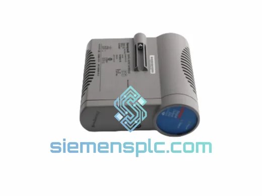
Honeywell FC-IO-0001 PLC I/O Module – FC Series
Safety Manager
Origin US
PLC I/O Module
Request verified availability, condition, replacement risk review, packing options and courier lead time for 2MLI-D28A-CC.
Click Request Quote and the part number is inserted into the inquiry form automatically.
Core fields for model confirmation and RFQ routing. Detailed product narrative remains below.
The Honeywell 2MLI-D28A-CC is a 28-channel discrete digital input/output module engineered for integration within the Honeywell Safety Manager (SM) platform — a dedicated safety logic solver certified to IEC 61508 SIL 2 and SIL 3. Within a safety-instrumented system (SIS), this module occupies the field-interface tier: it translates binary field-device states into backplane-readable data words and drives actuator commands from the logic solver to field-side output loads. Its role is not peripheral — it is the physical boundary at which the deterministic safety logic meets the stochastic process environment, and the integrity of that boundary directly governs the achievable safety integrity level of the overall safety function.
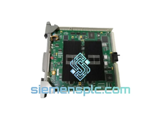
The module mounts into a single slot of the Safety Manager chassis backplane. Channel direction — input or output — is assigned at the engineering workstation level, with no hardware modification required. This software-defined channel allocation allows a single 2MLI-D28A-CC to simultaneously serve as the sensing interface for limit switches and pressure contacts while driving solenoid valve coils or motor contactor relays on the output side. For process units with mixed I/O density requirements, this eliminates the need to stock separate DI-only and DO-only module variants, simplifying spare-parts inventory management at the plant level.
The backplane communication protocol is a time-division multiplexed, slot-addressed bus proprietary to the Safety Manager chassis. Each module is assigned a fixed time slot within the SM scan cycle. The CPU reads all input channel states and writes all output channel commands within that slot boundary, guaranteeing that the I/O update latency is a fixed, calculable quantity — not a probabilistic estimate. This determinism is a hard requirement for SIL verification under IEC 61508-2, where the I/O response time must be explicitly bounded in the process safety time (PST) budget. Non-deterministic fieldbus protocols cannot satisfy this requirement without additional architectural measures; the 2MLI-D28A-CC’s backplane interface eliminates that complexity by design.
Real-time Stock & RFQ: [email protected] | WhatsApp: +86 18359268345
| Parameter | Specification |
|---|---|
| Part Number | 2MLI-D28A-CC |
| Manufacturer | Honeywell Process Solutions |
| Platform | Safety Manager (SM) Series |
| Module Function | 28-Channel Discrete Digital Input / Output |
| Channel Count | 28 (software-configurable DI or DO per channel) |
| Nominal Field Voltage | 24 VDC |
| DI Logic HIGH Threshold | 18–30 VDC |
| DI Logic LOW Threshold | < 5 VDC |
| DO Output Current (per channel) | 0.5 A continuous (resistive load) |
| Isolation Architecture | Optical isolation, channel-group galvanic separation |
| Backplane Interface | SM proprietary TDM backplane bus |
| Safety Integrity Level | SIL 2 / SIL 3 (IEC 61508, 1oo2D / 2oo3 voting) |
| Operating Temperature | 0 °C to +60 °C |
| Storage Temperature | −40 °C to +85 °C |
| Relative Humidity | 5–95 % RH, non-condensing |
| EMC Compliance | EN 61000-4 series; CE marked |
| RoHS Compliance | Compliant |
| Form Factor | Single-slot SM chassis card |
| Module Mass | 240 g |
| Warranty | 12 months from shipment date |
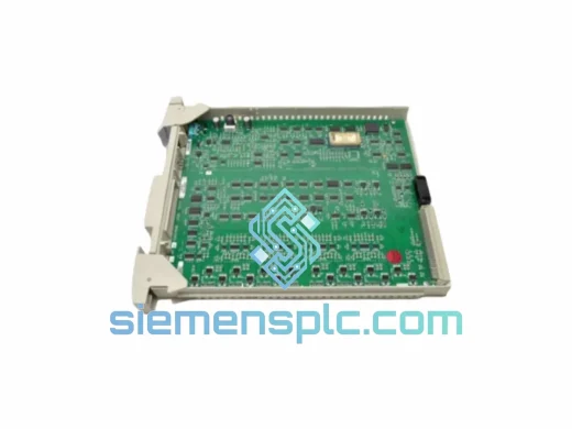
Galvanic Isolation via Optocoupler Stages: The 2MLI-D28A-CC separates field wiring from backplane logic through optocoupler-based galvanic isolation at the channel-group boundary. The LED side of each optocoupler is driven by the field-side signal conditioning circuit; the phototransistor side feeds the backplane logic domain. This topology breaks the conductive path between field wiring — which may carry inductive switching transients from solenoid valve de-energization, ground potential differences between field junction boxes and the control room, or capacitive discharge from long cable runs — and the internal CMOS logic circuitry. The isolation barrier is rated to withstand common-mode surge voltages consistent with EN 61000-4-5 Level 3 (2 kV line-to-earth), preventing field-side fault energy from reaching the safety logic solver.
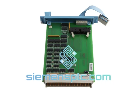
Input Signal Conditioning and Noise Rejection: Each digital input channel incorporates an RC low-pass filter network ahead of the optocoupler input stage. The filter cutoff is set to attenuate high-frequency conducted noise — particularly the switching harmonics generated by variable-frequency drives (VFDs) operating in the 2–20 kHz range — while preserving the signal bandwidth required to detect the fastest legitimate field-device state transitions. The filter time constant is selected to satisfy the debounce requirement for mechanical contacts (typically 10–20 ms) without introducing latency that would violate the process safety time budget. This dual constraint — noise rejection and response speed — is resolved at the hardware level, removing the need for software debounce routines in the SM application program.
Output Driver Architecture and Short-Circuit Protection: Digital output channels use solid-state driver circuits with integrated electronic current limiting. When the load current exceeds the rated 0.5 A threshold — as occurs during an output short-circuit or a wiring fault to a low-impedance path — the driver enters a current-limited operating mode and simultaneously asserts a fault flag in the module’s backplane status register. The CPU reads this flag within the next scan cycle and can execute the configured safe-state response. The current-limiting mechanism prevents thermal runaway in the driver transistor and eliminates the risk of a single output fault propagating thermal damage to adjacent channels on the same module.
PCB Ground Plane Partitioning: The module PCB uses a split ground plane strategy, physically separating the field-side return conductor from the logic-side ground pour. The two planes are connected only at a single, controlled star point through the isolation barrier, preventing field-side return currents from flowing through the logic ground and inducing common-impedance noise on the backplane data lines. This layout discipline is consistent with IEC 61000-4-6 conducted immunity requirements and is particularly important in installations where the field wiring shares cable trays with power conductors.
Continuous Internal Self-Test: The module executes background self-test routines during normal operation, verifying the functional integrity of the output driver circuits and the input signal conditioning paths without interrupting the I/O scan. Detected internal faults — including optocoupler degradation, driver circuit failures, and backplane communication errors — are reported to the SM CPU via the module status register. The CPU maps these fault flags to the application program’s diagnostic logic, enabling automatic safe-state transitions without requiring operator detection of the fault condition. This architecture contributes to the module’s diagnostic coverage (DC) metric, a key variable in the hardware fault tolerance (HFT) calculation required for SIL certification under IEC 61508-2 Table 3.
Each Honeywell 2MLI-D28A-CC unit shipped from our Xiamen, China operations center is processed through a structured pre-dispatch verification protocol. Label authentication confirms that the part number, revision level, and serial number are consistent with Honeywell’s production marking standards. Connector pin inspection verifies that backplane edge contacts are free of oxidation, mechanical deformation, or contamination that would impair electrical continuity after chassis insertion. Units are sourced exclusively through verified supply channels with documented traceability to authorized distribution or original equipment manufacturer stock.
Packaging adheres to ANSI/ESD S20.20 anti-static handling requirements: each module is sealed in a conductive ESD-protective bag, cushioned within a foam-lined corrugated carton, and accompanied by a humidity indicator card to confirm that storage conditions during transit remained within the manufacturer’s specified range. For international consignments, export documentation — commercial invoice, packing list, certificate of origin, and where applicable, an export control classification determination — is prepared in advance to minimize customs clearance delays at the destination port.
Carrier selection is matched to the urgency of the shipment: standard industrial deliveries are routed via DHL Express or FedEx International Priority, with typical transit times of 3–7 business days to major industrial centers in Europe, the Middle East, Southeast Asia, and the Americas. For critical plant maintenance scenarios where production loss costs exceed standard freight premiums, next-flight-out (NFO) arrangements are available on request. All units carry a 12-month warranty from the shipment date; confirmed manufacturing defects are resolved by replacement or credit without requiring return to the original manufacturer’s service network.
Email: [email protected]
WhatsApp: +86 18359268345
Web: siemensplc.com
Location: Xiamen, China
© 2026 siemensplc.com. All rights reserved.
We check the full part number, brand, series and visible nameplate information before quotation.
Sales confirms stock path, condition option, quantity and realistic lead time for export dispatch.
DHL, FedEx, UPS or buyer courier arrangements can be reviewed with packing requirements.
Similar brand or category products for fast comparison and multi-item RFQ lists.