Siemens
RFQ Ready
Siemens 6ES7321-1BL00-0AA0 Digital Input Module
SIMATIC
Origin DE
PLC Digital Input Module
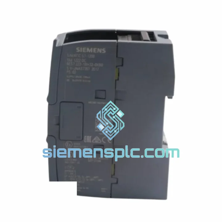
Request verified availability, condition, replacement risk review, packing options and courier lead time for 6ES7222-1HH32-0XB0.
Click Request Quote and the part number is inserted into the inquiry form automatically.
Core fields for model confirmation and RFQ routing. Detailed product narrative remains below.
The Siemens 6ES7222-1HH32-0XB0 is a 16-channel source-type (PNP) transistor digital output expansion module engineered for the SIMATIC S7-200 SMART compact PLC platform. Within a control loop, this module occupies the final execution layer: it receives discrete command signals from the CPU over the internal expansion bus and converts them into switched 24 VDC drive signals that actuate field devices — solenoid valves, motor contactors, indicator columns, and servo enable lines. Its role is deterministic and non-negotiable; any latency or signal integrity failure at this stage propagates directly into mechanical response error.
Unlike relay-output variants, the transistor architecture of the 6ES7222-1HH32-0XB0 eliminates mechanical contact bounce, supports sub-millisecond switching transitions, and sustains indefinite switching cycles without degradation. Each of the 16 output channels is rated at 0.75 A continuous, with a per-common group ceiling of 6 A — parameters that accommodate the inrush characteristics of inductive loads when paired with appropriate suppression diodes at the actuator terminals.
Real-time Stock & RFQ: [email protected] | WhatsApp: +86 18359268345
| Parameter | Specification |
|---|---|
| Part Number | 6ES7222-1HH32-0XB0 |
| Series | SIMATIC S7-200 SMART |
| Module Category | Digital Output (DO) Expansion |
| Number of Output Channels | 16 points |
| Output Transistor Type | PNP (Source / Sourcing) |
| Rated Output Voltage | 24 VDC |
| Output Voltage Range | 20.4 – 28.8 VDC |
| Max Current per Output Point | 0.75 A |
| Max Current per Common Group | 6 A |
| Output Isolation Method | Optical isolation (opto-coupler) |
| Switching Frequency (resistive load) | ≤ 1 kHz |
| Leakage Current (OFF state) | ≤ 10 µA |
| Voltage Drop (ON state) | ≤ 0.4 V |
| Expansion Bus Interface | S7-200 SMART proprietary expansion connector |
| Module Supply Voltage | 24 VDC (external or CPU-supplied) |
| Current Consumption (logic side) | ≤ 40 mA at 5 VDC from CPU bus |
| Operating Temperature | 0 °C to +55 °C |
| Storage Temperature | −40 °C to +70 °C |
| Relative Humidity | 5 % – 95 % (non-condensing) |
| Degree of Protection | IP20 |
| Dimensions (W × H × D) | 45 mm × 100 mm × 81 mm |
| Weight | Approx. 200 g |
| Mounting | 35 mm DIN rail (EN 60715) |
| Certifications | CE, UL, cUL, FM, RCM |
| Warranty | 12 months from date of shipment |
The internal architecture of the 6ES7222-1HH32-0XB0 is structured around three functional layers that operate in sequence on every scan cycle.
Expansion Bus Reception & Register Latching. The module receives output state data from the S7-200 SMART CPU via the proprietary parallel expansion bus. The bus operates at 5 VDC logic levels and transfers the 16-bit output image register in a single bus transaction per CPU scan. An internal latch register holds the output state between bus transactions, ensuring that field devices maintain their commanded state even during the brief inter-scan interval. This latch architecture prevents spurious output glitches that would otherwise occur if outputs were driven directly from a tri-state bus.
Opto-Coupler Isolation Stage. Each of the 16 channels passes through a dedicated opto-coupler before reaching the power transistor driver. The opto-coupler provides galvanic isolation between the 5 VDC logic domain (CPU bus side) and the 24 VDC field power domain (actuator side). The isolation barrier sustains a rated dielectric withstand voltage of 500 VAC (1 minute), which is sufficient to block common-mode transients generated by inductive load switching — motor contactors, solenoid valves, and relay coils — from coupling back into the CPU logic. The opto-coupler forward current is internally regulated, eliminating the need for external current-limiting resistors and simplifying PCB layout.
PNP Power Transistor Output Stage. The output transistor is a bipolar NPN device configured in a common-emitter topology with the collector connected to the 24 VDC supply rail and the emitter driving the load terminal — this is the electrical definition of PNP (source-type) behavior from the field wiring perspective. When the transistor saturates, the collector-emitter saturation voltage (V_CE(sat)) drops to ≤ 0.4 V, minimizing power dissipation within the module and reducing thermal stress on the PCB. The base drive circuit is designed to ensure full saturation at the rated 0.75 A load, maintaining a safe operating area margin across the full operating temperature range of 0 °C to 55 °C.
EMC Design Measures. The module PCB incorporates decoupling capacitors at each power supply pin, a common-mode choke on the 24 VDC input line, and a transient voltage suppressor (TVS) diode across the supply rails. These passive components collectively attenuate conducted emissions and provide immunity against fast transient bursts (IEC 61000-4-4, 2 kV) and electrostatic discharge (IEC 61000-4-2, 4 kV contact). The module housing is a flame-retardant thermoplastic with internal metal shielding clips that bond to the DIN rail ground, providing a low-impedance path for capacitively coupled high-frequency noise to chassis ground.
Thermal Management. At full load (16 channels × 0.75 A = 12 A aggregate, though limited to 6 A per common group), the power dissipation within the output transistors is approximately 16 × 0.4 V × 0.75 A = 4.8 W worst-case. The module housing incorporates ventilation slots aligned with natural convection airflow direction (bottom-to-top when mounted vertically on DIN rail), and the PCB thermal vias conduct heat from the transistor pads to the copper ground plane, which acts as a distributed heat spreader. No forced cooling is required within the rated operating temperature envelope.
The 6ES7222-1HH32-0XB0 delivers measurable advantages across eight dimensions of system performance:
Every Siemens 6ES7222-1HH32-0XB0 unit supplied by siemensplc.com is sourced through verified distribution channels and subjected to a structured pre-shipment verification protocol. Authenticity is confirmed by cross-referencing the module’s holographic label, date code, and firmware revision against Siemens AG’s official part traceability records. Physical inspection covers housing integrity, connector pin condition, and label legibility. Where test equipment is available, power-on verification confirms that the module enumerates correctly on the expansion bus and that all 16 output channels respond to commanded states.
Units are packaged in anti-static polyethylene bags, placed in foam-lined corrugated cartons, and sealed with tamper-evident tape. Each shipment includes a packing list with the part number, quantity, and serial/date code for customs documentation purposes. A 12-month warranty from the date of shipment covers manufacturing defects and premature failure under normal operating conditions.
Logistics operations are based in Xiamen, China — a major international port city with direct air freight connections to Frankfurt, Amsterdam, Dubai, Los Angeles, and Singapore. Standard international shipments are dispatched via DHL Express, FedEx International Priority, or UPS Worldwide Expedited, with typical transit times of 3–7 business days to Europe, North America, Southeast Asia, and the Middle East. Sea freight consolidation is available for bulk orders. Export documentation — commercial invoice, packing list, and certificate of origin — is prepared in compliance with destination country import requirements.
Email: [email protected]
WhatsApp: +86 18359268345
Web: siemensplc.com
Location: Xiamen, China
© 2026 siemensplc.com. All rights reserved.
We check the full part number, brand, series and visible nameplate information before quotation.
Sales confirms stock path, condition option, quantity and realistic lead time for export dispatch.
DHL, FedEx, UPS or buyer courier arrangements can be reviewed with packing requirements.
Similar brand or category products for fast comparison and multi-item RFQ lists.