Bently Nevada
RFQ Ready
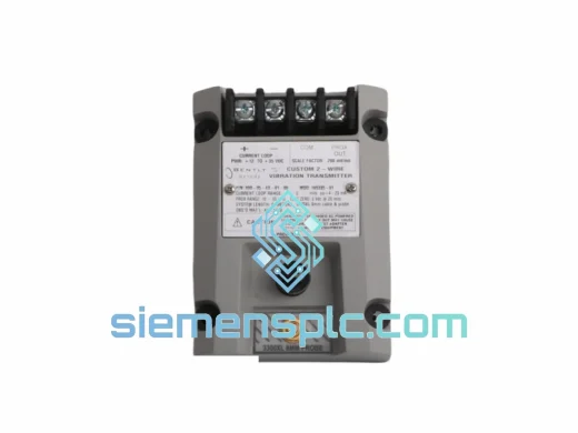
Bently Nevada RS901104-03-050-10-01 Proximitor Sensor – 3300 XL Series
3300 XL
Origin US
Proximitor Sensor
Request verified availability, condition, replacement risk review, packing options and courier lead time for 330709-000-030-10-02-00.
Click Request Quote and the part number is inserted into the inquiry form automatically.
Core fields for model confirmation and RFQ routing. Detailed product narrative remains below.
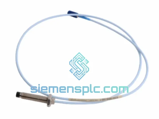
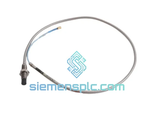
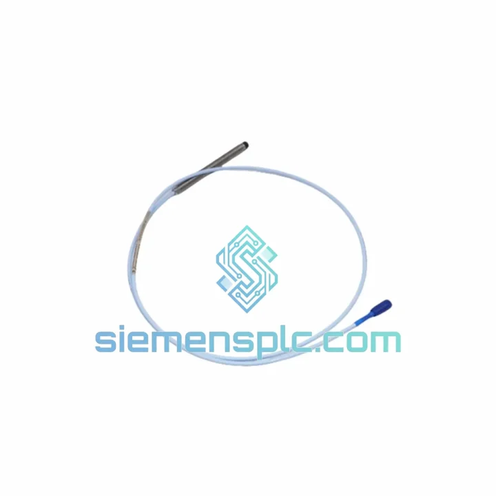
The 330709-000-030-10-02-00 is a 10 mm tip-diameter, non-contact eddy-current displacement transducer manufactured by Bently Nevada (Baker Hughes) as part of the 3300 XL Proximity Transducer System. Its primary function within a machinery protection control loop is to deliver a continuous, high-resolution analog voltage proportional to the radial air gap between the probe tip and a rotating shaft journal. This signal serves as the raw measurement input for shaft radial vibration, shaft relative position (eccentricity), and differential shaft expansion monitoring — three of the four primary parameters mandated by API 670 (5th Edition) for turbomachinery protection systems.
The transduction mechanism relies on a high-frequency LC oscillator embedded in the probe body, operating at approximately 1.0 MHz carrier frequency. The oscillator drives a flat coil wound at the probe tip, projecting an alternating electromagnetic field into the target zone. When a conductive, ferromagnetic shaft surface (typically AISI 4140 low-alloy steel, σ ≈ 4.5 MS/m, μr ≈ 100) enters this field, eddy currents are induced at the shaft surface. These eddy currents extract energy from the oscillator circuit, reducing its tank circuit Q-factor and shifting the oscillator output amplitude in direct proportion to the gap distance. The Proximitor® sensor — a separate signal conditioning module (e.g., 330180 or 330181 series) — demodulates this amplitude-modulated carrier and outputs a calibrated DC voltage: −2 VDC at minimum gap (0.25 mm / 10 mil) to −22 VDC at maximum gap (2.54 mm / 100 mil), with a nominal sensitivity of 7.87 V/mm (200 mV/mil).
Within the 3500 Series Machinery Protection System, this buffered DC signal is sampled by the monitor’s analog input stage at rates sufficient to resolve vibration frequencies up to 20 kHz. The monitor applies configurable alert and danger setpoints to the real-time gap voltage, executing relay-based trip logic within deterministic scan cycles. The 330709-000-030-10-02-00’s 3.0 m integrated armored cable is factory-matched to the 3300 XL system’s cable loop impedance specification; the total probe-plus-extension cable length must remain within the Proximitor® sensor’s validated range to preserve calibration accuracy — a constraint that makes the 3.0 m suffix a deliberate engineering selection, not an arbitrary length.
Real-time Stock & RFQ: [email protected] | WhatsApp: +86 18359268345
| Parameter | Specification |
|---|---|
| Part Number | 330709-000-030-10-02-00 |
| Brand / Manufacturer | Bently Nevada (Baker Hughes) |
| Product Series | 3300 XL Proximity Transducer System |
| Transducer Type | Eddy-Current (Inductive) Non-Contact Displacement Probe |
| Tip Diameter | 10 mm |
| Thread Specification | M10 × 1.0 (metric fine) |
| Integrated Cable Length | 3.0 m (9.84 ft), armored coaxial |
| Nominal Sensitivity | 7.87 V/mm (200 mV/mil) |
| Linear Measurement Range | 0.25 mm – 2.54 mm (10 – 100 mil) |
| Linearity Error | ≤ ±1% of full-scale range (AISI 4140 target) |
| Carrier Frequency | ~1.0 MHz (internal LC oscillator) |
| Supply Voltage | −24 VDC nominal (sourced from Proximitor® sensor) |
| Output Voltage Range | −2 VDC to −22 VDC (gap-dependent) |
| Sensitivity Drift (Thermal) | ≤ ±0.5% over full temperature range |
| Operating Temperature — Probe Body | −35 °C to +177 °C |
| Operating Temperature — Cable | −35 °C to +121 °C |
| Target Material (Standard Cal.) | AISI 4140 steel (σ ≈ 4.5 MS/m, μr ≈ 100) |
| Probe Body Material | 316L stainless steel |
| Skin Depth at 1.0 MHz (AISI 4140) | ~8 μm |
| Ingress Protection | IP67 (probe body and connector) |
| Connector Interface | Integral coaxial, 3300 XL-series compatible |
| Hazardous Area Approvals | ATEX, FM (Zone 1 / Div. 1 with approved barriers) |
| Regulatory Compliance | API 670 (5th Ed.), IEC 61511, CE |
| Compatible Proximitor® Sensors | 330180, 330181 series |
| Compatible Monitor | Bently Nevada 3500 Series MPS |
| Warranty | 12 months from shipment date against manufacturing defects |
Thermal Compensation Architecture in the Oscillator Stage: The probe tip assembly integrates a negative-temperature-coefficient (NTC) resistor network in series with the LC tank circuit. As probe body temperature rises, the NTC element reduces its resistance, partially offsetting the inductance increase caused by thermal expansion of the coil former. This passive compensation scheme maintains sensitivity within ±0.5% across the −35 °C to +177 °C envelope without requiring active electronics at the probe tip — a deliberate design choice that eliminates failure modes associated with active components in high-temperature bearing housing environments. Steam turbine bearing pedestals routinely expose proximity probes to 150 °C ambient during full-load operation; the passive NTC approach provides compensation without adding a potential failure point.
Coaxial Cable Impedance Matching and Loop Resistance Budget: The 3.0 m armored coaxial cable is manufactured to a controlled characteristic impedance (nominally 50 Ω) and a defined DC loop resistance. The Proximitor® sensor’s internal oscillator drive circuit is calibrated against a specific cable loop resistance range; deviating from the specified total cable length (probe cable + extension cable) shifts the oscillator’s operating point, introducing a systematic sensitivity error that cannot be corrected by the monitor’s channel gain adjustment alone. The 330709-000-030-10-02-00’s 3.0 m suffix is therefore a system-level parameter, not merely a physical convenience — it defines the probe’s position in the Proximitor® sensor’s cable length lookup table used during factory calibration.
Single-Point Shield Grounding and Ground-Loop Rejection: The coaxial cable shield is bonded to the probe body at the tip end and terminated at the Proximitor® sensor chassis ground at the opposite end. This single-point grounding topology prevents circulating ground-loop currents — which would appear as 50/60 Hz or harmonic noise on the displacement signal — from flowing through the shield conductor. In compressor train installations where the probe mounting bracket is at a different ground potential than the control room panel (a common condition in large petrochemical plants with distributed grounding systems), this architecture maintains signal integrity without requiring isolation transformers or active ground-loop breakers.
Eddy-Current Skin Effect and Surface Sensitivity: At 1.0 MHz, the electromagnetic skin depth in AISI 4140 steel is approximately 8 μm. This means the probe’s measurement field interacts exclusively with the outermost 8 μm of the shaft surface. Practical consequences: (1) surface plating, chrome or nickel coatings alter the effective conductivity and permeability seen by the probe, requiring recalibration if coating thickness exceeds ~5 μm; (2) residual magnetism in the shaft journal from prior magnetic particle inspection (MPI) introduces a permeability non-uniformity that manifests as a once-per-revolution (1×) vibration component — a known artifact that must be distinguished from true mechanical unbalance during commissioning; (3) the probe is inherently insensitive to subsurface shaft defects, making it a displacement-only transducer rather than a structural health sensor.
Mechanical Mounting Torque and Ceramic Tip Integrity: The M10 × 1.0 thread engages standard API 670 proximity probe mounting brackets. The probe body incorporates a 14 mm wrench flat for controlled torque application. Recommended installation torque is 5–8 N·m depending on bracket material (aluminum vs. steel). Over-torque beyond 10 N·m risks fracturing the alumina ceramic tip insert that houses the sensing coil — a failure mode that produces an immediate open-circuit condition detectable by the Proximitor® sensor’s gap voltage rail-to-rail output, but which requires probe replacement rather than field repair.
All Bently Nevada 330709-000-030-10-02-00 units supplied through siemensplc.com are sourced through documented industrial distribution channels with verifiable chain of custody. Pre-shipment inspection covers: part number label verification against manufacturer markings, connector pin integrity and coaxial cable continuity measurement, probe body thread condition, ceramic tip surface inspection under magnification, and cable jacket abrasion assessment. Units exhibiting label inconsistencies, connector corrosion, or tip surface damage are quarantined and not dispatched.
Packaging protocol: individual anti-static foam-lined boxes with moisture-desiccant sachets, sealed in tamper-evident outer cartons. Original manufacturer packaging is retained where available. Each shipment is accompanied by a commercial invoice, packing list, certificate of origin (Xiamen, Fujian, China), and HS Code 8543.70.9000 export classification documentation. Factory calibration certificates are provided on request.
Our dispatch facility is located in the Xiamen Fujian Free Trade Zone, with direct carrier contracts covering DHL Express (1–3 day delivery to most destinations), FedEx International Priority, UPS Worldwide Express, and consolidated LCL/FCL sea freight for bulk orders. In-stock units are dispatched within 1–3 business days of payment confirmation. We have fulfilled orders to industrial customers in over 60 countries across Southeast Asia, the Middle East, Europe, North America, and South America. Export compliance documentation is prepared to meet destination country customs requirements, including MSDS and dual-use screening where applicable.
Warranty Terms: 12 months from shipment date against manufacturing defects in materials and workmanship. Warranty claims require photographic documentation of the defect and the original shipment label. Warranty does not cover damage from improper installation torque, operation outside the specified temperature or voltage envelope, or physical impact to the probe tip. Unused, unopened units may be returned within 30 days with prior written authorization (RMA number required).
Email: [email protected]
WhatsApp: +86 18359268345
Web: siemensplc.com
Location: Xiamen, China
© 2026 siemensplc.com. All rights reserved.
We check the full part number, brand, series and visible nameplate information before quotation.
Sales confirms stock path, condition option, quantity and realistic lead time for export dispatch.
DHL, FedEx, UPS or buyer courier arrangements can be reviewed with packing requirements.
Similar brand or category products for fast comparison and multi-item RFQ lists.