Bently Nevada
RFQ Ready
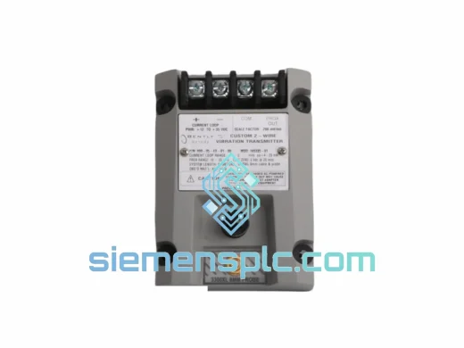
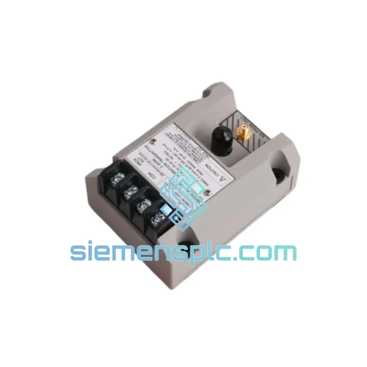
Bently Nevada RS901104-03-050-10-01 Proximitor Sensor – 3300 XL Series
3300 XL
Origin US
Proximitor Sensor
Request verified availability, condition, replacement risk review, packing options and courier lead time for 901100-90-03.
Click Request Quote and the part number is inserted into the inquiry form automatically.
Core fields for model confirmation and RFQ routing. Detailed product narrative remains below.
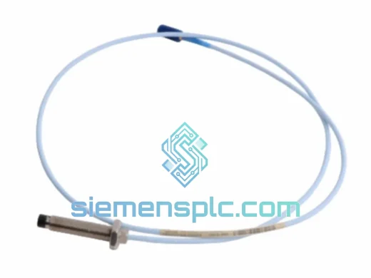
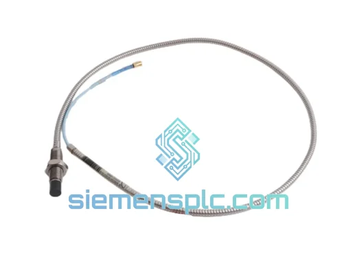
The Bently Nevada 901100-90-03 is a factory-terminated, 90-inch (2,286 mm) coaxial extension cable designed as a precision passive element within the 3300 XL Proximity Transducer System. Its function is to bridge the gap between the probe’s integral cable connector and the Proximitor® sensor input while preserving the electrical characteristics upon which the entire measurement chain depends. In an eddy current displacement measurement loop, the extension cable is not a generic conductor — it is a calibrated transmission-line segment whose impedance, distributed capacitance, and dielectric stability are engineered to maintain the Proximitor® sensor’s transfer function within factory-specified tolerances.
The 3300 XL system drives the probe tip at carrier frequencies ranging from approximately 200 kHz (8 mm probe) to higher frequencies for smaller-gap configurations. At these frequencies, any passive cable segment behaves as a distributed-parameter transmission line. The characteristic impedance Z₀ = √(L’/C’) — where L’ is distributed inductance per unit length and C’ is distributed capacitance per unit length — must remain matched to the Proximitor® sensor’s source impedance. A mismatch of even a few percent introduces standing wave reflections that compress the linear measurement range and introduce a DC offset error, corrupting both static gap readings and dynamic vibration amplitude data delivered to the monitor rack.
At 90 inches, the 901100-90-03 addresses the most prevalent installation geometry in turbomachinery bearing housings: the Proximitor® sensor mounted outside the high-temperature zone, with the probe tip positioned at the shaft journal. The armored outer jacket distributes mechanical loads — from cable tray crush, adjacent piping abrasion, and casing thermal growth cycles — across the armor layer before they reach the coaxial dielectric, preserving the controlled geometry that defines the cable’s electrical parameters throughout its service life.
Real-time Stock & RFQ: [email protected] | WhatsApp: +86 18359268345
| Part Number | 901100-90-03 |
| Manufacturer | Bently Nevada (Baker Hughes) |
| Compatible System | 3300 XL Proximity Transducer System |
| Cable Role in Signal Chain | Extension segment: probe integral cable connector → Proximitor® sensor input |
| Nominal Cable Length | 90 in (2,286 mm) |
| Cable Architecture | Coaxial; controlled-geometry dielectric; continuous braided shield; armored outer jacket |
| Connector Termination | Factory pre-terminated both ends; OEM-matched coaxial interface |
| Impedance Matching | Matched to 3300 XL Proximitor® sensor input specification |
| System Sensitivity (nominal) | –200 mV/mil (–7.87 V/mm) when used with calibrated 3300 XL probe and Proximitor® |
| Operating Temperature Range | –50 °C to +120 °C |
| Compatible Probe Series | 3300 XL 8 mm, 11 mm, 14 mm, 25 mm proximity probes |
| Jacket Chemical Resistance | ISO VG 32–68 turbine oils, synthetic lubricants, common maintenance solvents |
| Regulatory Compliance | API 670 (Machinery Protection Systems) |
| Approximate Weight | 800 g |
| Country of Origin | United States |
| Warranty | 12 months against manufacturing defects from date of dispatch |
The coaxial geometry of the 901100-90-03 is its primary engineering asset. The center conductor-to-shield spacing is held to tight dimensional tolerances along the full 90-inch run. Any localized deformation — an overtorqued cable clamp, a pinch point in a conduit, or a crush event in a cable tray — alters the local C’ value, creating a discrete impedance discontinuity at that point. The reflected wave from this discontinuity travels back toward the Proximitor® sensor input and superimposes on the forward signal, producing a frequency-dependent measurement error that is difficult to distinguish from genuine shaft motion at the monitor output. The armored jacket construction of the 901100-90-03 prevents this failure mode by absorbing mechanical loads at the armor layer before they reach the dielectric.
The factory connector terminations eliminate the single largest source of field-introduced impedance mismatch. A field-assembled coaxial connector introduces variability in three critical dimensions: center-conductor protrusion length, dielectric gap between center conductor and connector body, and shield contact resistance at the crimp or solder joint. Each variable contributes to a connector-level impedance discontinuity. The 901100-90-03’s pre-terminated connectors are assembled under controlled conditions with dimensional verification, producing a repeatable connector impedance that matches the Proximitor® sensor’s input specification without field adjustment.
The braided shield is bonded at both connector ends, providing a continuous low-impedance return path. In modern plant electrical environments — where variable-frequency drives, high-current motor leads, and bus bars often share cable trays with instrumentation wiring — common-mode electromagnetic interference is a persistent noise source. A shield with a high-resistance bond at either end acts as an antenna rather than a barrier; the 901100-90-03’s dual-end bonding ensures the shield functions as a Faraday enclosure across the full carrier frequency range of the 3300 XL system.
The dielectric material’s permittivity stability across the –50 °C to +120 °C operating range is a less-discussed but operationally significant parameter. Permittivity drift with temperature directly changes C’ and therefore Z₀. In a cable that experiences a 170 °C temperature swing across a turbine start-stop cycle, a dielectric with poor thermal permittivity stability introduces a slow DC offset drift in the gap channel that can be misinterpreted as bearing wear or rotor thermal bow during the transient period.
Each 901100-90-03 unit dispatched from our Xiamen, China operations base is sourced from authorized distribution channels and verified OEM surplus inventory. Pre-dispatch inspection covers visual examination of both connector bodies for corrosion or mechanical damage, jacket integrity check along the full cable length for cracking or chemical attack, and connector mating force verification to confirm the connector retains its specified engagement force. Units that do not pass all inspection criteria are rejected and withheld from sale.
Documentation available upon request includes certificate of conformance, lot traceability records to the original Bently Nevada manufacturing batch, and the applicable product specification sheet. For facilities operating under ISO 55001 asset management programs or maintaining API 670 documentation packages, this traceability chain integrates directly into the required maintenance records without additional procurement steps or third-party verification.
International freight is managed through DHL Express, FedEx International Priority, and UPS Worldwide Expedited, with standard dispatch lead time of 3–5 business days from order confirmation. For forced-outage or plant emergency scenarios, same-day dispatch is available for confirmed in-stock units — contact us directly via WhatsApp for real-time inventory status and expedited freight quotation. Export documentation — commercial invoice, packing list, certificate of origin — is prepared in compliance with destination country import requirements. HS Code 8544.42 applies to this product category in most jurisdictions.
Email: [email protected]
WhatsApp: +86 18359268345
Web: siemensplc.com
Location: Xiamen, China
© 2026 siemensplc.com. All rights reserved.
We check the full part number, brand, series and visible nameplate information before quotation.
Sales confirms stock path, condition option, quantity and realistic lead time for export dispatch.
DHL, FedEx, UPS or buyer courier arrangements can be reviewed with packing requirements.
Similar brand or category products for fast comparison and multi-item RFQ lists.