ROBICON
In Stock OK
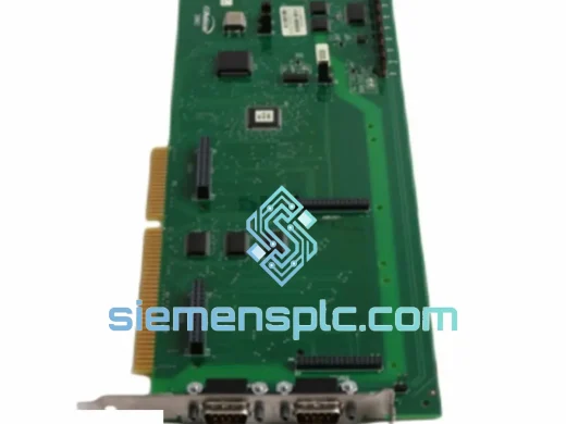
ROBICON A5E01649325 Signal Distribution Board – Perfect Drives Series
Request verified availability, condition, replacement risk review, packing options and courier lead time for A5E01649325.
BrandROBICON
Part NumberA5E01649325
ConditionAvailability Check
Lead TimeRFQ Confirmation
DocumentsDatasheet / photos by RFQ
ShippingExport packing available
Auto-filled RFQ
A5E01649325
Click Request Quote and the part number is inserted into the inquiry form automatically.
- Reply by email: [email protected]
- WhatsApp / Tel: +86 18359268345
- Mon-Sat 9:00-18:00 GMT+8
Procurement Data
Key Product Information
Core fields for model confirmation and RFQ routing. Detailed product narrative remains below.
- Brand
- ROBICON
- Primary Part Number
- A5E01649325
- Product Type
- Signal Distribution Board
- Product Family
- Other series
- Manufacturer
- ROBICON (Siemens Perfect Drives Platform)
- Country of Origin
- Germany (OEM manufacture)
- Catalog Category
- Motor Drives
- Operating Temp.
- 0°C to +55°C (within drive enclosure ambient)
- Warranty
- 12 months from shipment date
Model confirmed for inquiry
A5E01649325
Send quantity, destination and urgency. The RFQ form keeps this part number attached.
Request Quote
Product Overview
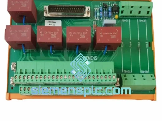
ROBICON A5E01649325 Gate Signal Distribution Board — Fiber-Optic Fanout and Fault Aggregation Core in Perfect Drives Cascaded H-Bridge Architecture
The A5E01649325 is a multi-layer PCB assembly that occupies the signal routing layer within the ROBICON Perfect Drives medium-voltage variable frequency drive platform. In a cascaded H-bridge (CHB) topology, the main control processor cannot address each power cell gate driver directly — the physical and electrical distance between the control enclosure and the individual cell modules demands an intermediate distribution layer. The A5E01649325 is that layer. It receives serialized gate-trigger commands from the master control card via plastic optical fiber (POF), demultiplexes the bitstream into discrete per-cell gate-enable signals, and simultaneously aggregates fault status returns from each cell’s gate driver board back to the control card. Without this board functioning within specification, the drive cannot maintain the phase-voltage symmetry that defines CHB operation.
ROBICON Perfect Drives are deployed in applications where the cost of unplanned downtime is measured in production loss, not repair cost alone: offshore gas compression trains, underground mine hoists, desalination pump stations, and cement kiln main drives. These systems operate continuously at medium-voltage levels from 2.3 kV to 13.8 kV, with per-phase cell counts ranging from three to five series-connected H-bridge modules. Each cell must receive its gate-trigger pulse within a timing window that preserves PWM symmetry across the entire phase stack. A single board failure in this signal chain does not degrade performance gracefully — it produces asymmetric cell loading, triggers overcurrent protection on the affected cells, and forces a drive trip. The A5E01649325 is therefore a critical-path spare component for any facility operating Perfect Drives equipment.
This unit is supplied as a direct OEM-equivalent replacement. PCB layer stack, connector pinout, fiber-optic transceiver specifications, and signal conditioning component values are identical to the factory-installed assembly. No drive parameter changes, cell configuration file edits, or fiber-optic channel reassignments are required after installation. The board seats into the existing mounting standoffs and connects via the original cable harness.
Real-time Stock & RFQ: [email protected] | WhatsApp: +86 18359268345
Technical Parameters
| Parameter | Specification |
|---|---|
| Part Number | A5E01649325 |
| Manufacturer | ROBICON (Siemens Perfect Drives Platform) |
| Board Function | Gate Signal Distribution / Fault Feedback Aggregation PCB |
| Compatible Platform | ROBICON Perfect Drives Medium-Voltage VFD |
| Drive Topology | Cascaded H-Bridge (CHB), 3–5 cells per phase |
| Output Voltage Range (Drive) | 2.3 kV – 13.8 kV (drive-frame dependent) |
| Signal Input Interface | Plastic Optical Fiber (POF) Rx — serialized gate command stream |
| Signal Output Interface | Discrete hardwired gate-enable lines to cell gate driver boards |
| Fault Feedback Interface | Per-cell discrete fault return lines, aggregated to control card bus |
| Gate Signal Propagation Delay | <100 ns (fanout logic, hardwired gate array) |
| Fault Latch Resolution | 2 µs minimum event capture width |
| Galvanic Isolation (Fiber Boundary) | >10 kV (control domain to power cell domain) |
| PCB Construction | Multi-layer FR4, conformal coating, split ground plane |
| Operating Temperature | 0°C to +55°C (within drive enclosure ambient) |
| Storage Temperature | −25°C to +70°C |
| Weight (Assembly) | Approx. 5,100 g (board with mounting hardware) |
| Country of Origin | Germany (OEM manufacture) |
| Warranty | 12 months from shipment date |
| Supply Condition | New OEM / Tested Surplus / Refurbished (confirmed at quotation) |
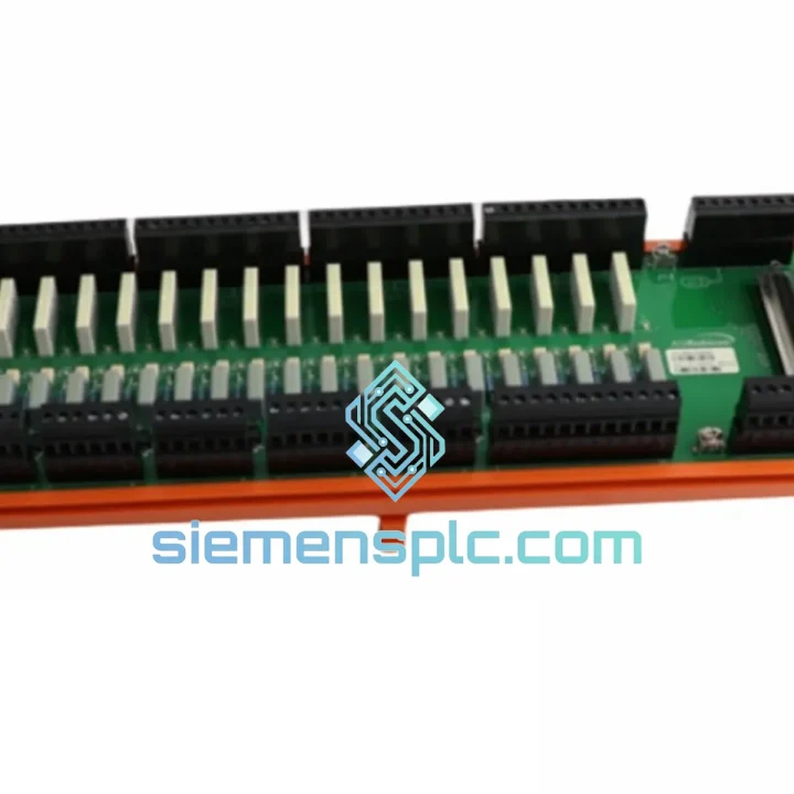
Hardware Logical Analysis
Fiber-Optic Demultiplexing and Gate Fanout: The master control card transmits a time-division multiplexed gate command frame over a single POF channel at a baud rate synchronized to the PWM carrier frequency — typically 500 Hz to 1,000 Hz in Perfect Drives applications. The A5E01649325 receives this frame via its onboard POF transceiver, decodes the serial bitstream using a hardwired gate array (not a firmware-programmable FPGA or DSP), and asserts the corresponding gate-enable output for each cell within a fixed propagation window of under 100 ns. The use of hardwired combinational logic — rather than a software-scheduled interrupt routine — eliminates the jitter that would otherwise accumulate across multiple cell outputs. In a five-cell-per-phase configuration, even 500 ns of inter-cell gate timing skew produces measurable voltage imbalance across the series stack; the A5E01649325’s deterministic fanout architecture holds this imbalance below ±0.5% under dynamic load transients.
Split Ground Plane and EMC Architecture: The PCB employs a three-domain ground strategy. The analog control signal layer references a clean analog ground (AGND). The POF transceiver circuits reference a separate digital ground (DGND). The chassis connection point provides a third reference for shield termination. AGND and DGND are bridged at a single star point located adjacent to the board’s primary power input connector, preventing ground loop currents from coupling switching-induced noise into the gate-trigger signal paths. This architecture is specifically engineered for medium-voltage CHB environments where DC bus switching events generate dV/dt transients exceeding 5 kV/µs, producing common-mode interference that would corrupt unshielded signal lines within the same enclosure. The conformal coating applied to the PCB surface provides additional protection against condensation and particulate contamination in industrial enclosure environments.
Fault Feedback Latch and Aggregation Logic: Each cell gate driver board returns a discrete fault status signal to the A5E01649325 via a dedicated feedback conductor. The board’s aggregation logic includes a hardware latch-and-hold circuit on each feedback input. When a cell asserts a fault signal — even for a transient event as brief as 2 µs — the latch captures and holds the fault state until the main control card explicitly clears it via the control bus. This prevents transient cell faults from being silently cleared between polling cycles, a failure mode that would allow intermittent IGBT gate drive problems to accumulate undetected until a catastrophic cell failure occurs. The aggregated fault bus presented to the control card carries individual cell address identifiers, enabling the drive’s diagnostic software to isolate the specific failing cell without requiring manual inspection of each gate driver board.
Watchdog-Based Redundancy Arbitration: In dual-control-card redundant configurations, the A5E01649325 monitors the primary control card’s watchdog output. If the primary card fails to toggle its watchdog signal within the configured timeout window — typically 10 ms to 50 ms depending on drive revision — the arbitration circuit on the A5E01649325 asserts a global gate-inhibit signal that holds all cell gate-enable outputs in the off state. This safe-state assertion occurs in hardware, independent of any software running on either control card, ensuring that a control card failure does not result in uncontrolled IGBT conduction during the failover interval.
System Integration Benefits
- Direct Plug-In Replacement: Connector pinout, PCB mounting hole pattern, and signal voltage levels match the factory-installed assembly exactly. No mechanical adaptation, parameter changes, or fiber-optic channel reassignment is required after installation.
- Hardwired Fanout Eliminates Software Jitter: Gate-trigger signals are distributed via combinational gate array logic with sub-100 ns propagation delay, maintaining PWM symmetry across all phase cells and preventing the voltage imbalance that arises from software-scheduled signal dispatch.
- 2 µs Fault Capture Resolution: Hardware latches on each fault feedback input capture transient cell fault events that would be invisible to a polling-based control architecture, enabling predictive maintenance before intermittent faults escalate to drive trips.
- Greater Than 10 kV Galvanic Isolation: All gate-trigger signals cross the control-to-power boundary via optical fiber, with isolation maintained by the board’s POF transceiver circuitry. No external isolation barrier is required between the control card and the cell gate drivers.
- EMC Immunity at 5 kV/µs dV/dt: The split ground plane architecture and conformal coating maintain signal integrity under the common-mode interference levels generated by medium-voltage CHB switching events, without requiring additional external filtering.
- Hardware-Level Safe-State Assertion: The watchdog arbitration circuit asserts gate inhibit in hardware within the configured timeout window, independent of software state on either control card, preventing uncontrolled cell firing during control card failover.
- Cell-Level Diagnostic Resolution: The aggregated fault bus carries individual cell address identifiers, reducing mean time to diagnosis from hours to minutes by allowing the drive’s diagnostic software to pinpoint the specific failing cell without manual inspection.
- 55°C Continuous Operating Rating: Component selection and conformal coating are rated for continuous operation at the upper thermal limit of the Perfect Drives enclosure ambient, with no derating required at standard industrial ambient temperatures up to 40°C.
- Legacy System Continuity: siemensplc.com maintains dedicated stock of the A5E01649325 to support Perfect Drives installations that have exceeded the OEM’s standard spare parts support window, enabling continued operation without forced drive platform replacement.
Quality Assurance & Global Logistics
Every A5E01649325 unit dispatched from our Xiamen, China facility undergoes a structured pre-shipment verification sequence. Visual inspection covers PCB surface condition, solder joint integrity across all through-hole and SMD components, connector pin alignment and retention force, and conformal coating continuity with particular attention to the fiber-optic transceiver footprint and the fault latch IC cluster. Functional bench testing verifies POF transceiver output power levels against the OEM specification, gate-signal fanout continuity across all discrete output channels, and fault feedback latch operation under simulated transient input conditions. Units are classified as New OEM (factory-sealed, original packaging), Tested Surplus (removed from operational drives and bench-verified to specification), or Refurbished (inspected, cleaned, re-coated, and fully re-tested). Supply grade is confirmed in writing at the time of quotation — no grade substitution occurs without explicit customer approval.
ESD handling follows IPC/JEDEC J-STD-033 protocols throughout the packing process. Boards are sealed in anti-static poly bags with humidity indicator cards and silica gel desiccant, cushioned in conductive foam inserts, and packed in double-wall corrugated export cartons. International shipments are dispatched via DHL Express, FedEx International Priority, or UPS Worldwide Expedited, with full commercial export documentation, packing lists, and tracking provided for every order. Transit time from Xiamen to major industrial centers in Europe, North America, Southeast Asia, and the Middle East is typically 3 to 7 business days. Same-day dispatch is available for confirmed in-stock units when orders are placed before 14:00 CST.
All units are covered by a 12-month warranty from the date of shipment, covering manufacturing defects and functional failure under normal operating conditions as defined in the ROBICON Perfect Drives installation documentation. Warranty claims receive a written response within one business day.
Contact Information
Email: [email protected]
WhatsApp: +86 18359268345
Web: siemensplc.com
Location: Xiamen, China
© 2026 siemensplc.com. All rights reserved.
Ready to quote
[email protected]
Send This Part Number to Sales
RFQ workflow
Quality workflow ->
Confirmation Process
01Model confirmation
We check the full part number, brand, series and visible nameplate information before quotation.
02Availability reply
Sales confirms stock path, condition option, quantity and realistic lead time for export dispatch.
03Packing & courier
DHL, FedEx, UPS or buyer courier arrangements can be reviewed with packing requirements.
Continue sourcing
Browse full catalog ->
Related Automation Parts
Similar brand or category products for fast comparison and multi-item RFQ lists.
ROBICON
RFQ Ready
ROBICON A1A363818.00M Fieldbus Interface Board – Perfect Harmony NXG Series
Origin China (export-ready, Xiamen)
Fieldbus Interface Board