Yokogawa
RFQ Ready
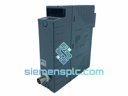
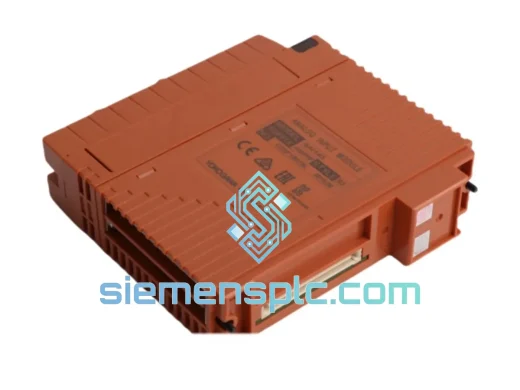
Yokogawa SAI143-H63/PRP S3 DCS Analog Input Module
CENTUM VP
Origin JP
DCS Analog Input Module
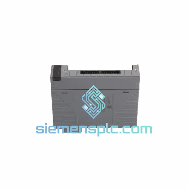
Request verified availability, condition, replacement risk review, packing options and courier lead time for AAI543-S03.
Click Request Quote and the part number is inserted into the inquiry form automatically.
Core fields for model confirmation and RFQ routing. Detailed product narrative remains below.
The Yokogawa AAI543-S03 S1 is an eight-channel analog output module designed for single-slot installation within CENTUM VP and CENTUM CS 3000 node units. Each channel independently sources a 4–20 mA DC signal into a field wiring loop, converting a 16-bit digital setpoint — received from the Field Control Station over the node unit’s internal bus — into a proportional loop current with a full-scale accuracy of ±0.1% FS. The module draws all operating power from the backplane bus; no external field-side supply is required for the output stage. The -S03 suffix identifies the CE-marked variant, confirming conformity with EMC Directive 2014/30/EU and Low Voltage Directive 2014/35/EU. The S1 hardware revision designation is traceable through Yokogawa’s manufacturing records and is required for firmware compatibility verification and spare-part ordering through Yokogawa’s global service network.
Within a CENTUM VP Field Control Station, the control execution engine runs PID, cascade, feedforward, or model-based algorithms at a configurable scan period (100 ms to 1,000 ms). At the end of each scan, computed manipulated variable (MV) values are written to the node unit’s internal register map. The AAI543-S03 S1 reads these register values via the ESB (Extended Serial Backplane) or V-net/IP bus interface, latches them into a double-buffer, and transfers the buffered digital word to the per-channel 16-bit D/A converter at the start of the next output update cycle. This double-buffering mechanism prevents mid-cycle register updates from causing transient current glitches at the field terminals — a measurable concern in tight flow or pressure control loops where even a 1 mA transient can produce a visible process disturbance at a valve positioner.
The resulting analog voltage from the D/A stage is fed into a voltage-to-current (V/I) conversion amplifier. The V/I stage maintains loop current accuracy across the full 0–750 Ω load resistance range by using a feedback sense resistor in series with the output terminal, continuously correcting for load impedance variation. This architecture means that the module’s ±0.1% FS accuracy specification holds regardless of whether the field device presents 100 Ω or 700 Ω to the loop — a practical advantage in plants where cable runs of varying length connect the I/O cabinet to actuators at different distances.
Channel isolation is implemented using a per-channel isolated DC-DC converter topology. Each output channel’s analog circuitry — including the V/I amplifier and the sense resistor — operates from a floating supply derived from the backplane bus through a miniature transformer. The output common of each channel is therefore electrically independent from the module ground, the backplane bus reference, and all other channel commons. In multi-train process plants where actuators from different control loops share a common negative rail in the field junction box, this floating-output architecture eliminates the need for external loop isolators in the marshalling cabinet, reducing component count and panel wiring complexity.
The S1 hardware revision introduced a common-mode choke on the field wiring interface of each channel, in addition to the transient voltage suppression (TVS) diodes and ferrite bead filtering already present on the bus interface lines. This modification improved conducted emission margins by approximately 6 dB relative to the original hardware release — a measurable benefit in installations where variable-frequency drives, large motor starters, or high-current switching equipment are located in adjacent panels or share the same cable tray infrastructure. The PCB layout partitions the digital processing section from the analog output section using a split ground plane, with a single-point connection at the power supply reference, minimizing capacitive coupling of digital switching noise into the analog output signal path.
Diagnostic logic embedded in the module’s onboard microcontroller monitors each output channel continuously. An open-circuit condition — indicated by loop current falling below 3.6 mA when the setpoint is above the fault threshold — is detected within one scan cycle and reported to the FCS as a channel-level fault flag. The FCS alarm management system receives this flag as a structured diagnostic object and can execute a pre-configured fault response: hold last value, drive to a defined safe-state current, or generate an operator alarm with channel identification. This closed-loop diagnostic path eliminates the need for manual loop continuity checks during normal operation and reduces mean time to repair (MTTR) by directing maintenance personnel directly to the faulted channel and terminal block.
The module supports NAMUR NE 43 fault state signaling. Output channels can be configured to drive to 3.6 mA (low fault state) or 21.0 mA (high fault state) upon FCS-commanded fault, providing unambiguous fault indication to HART-capable valve positioners and smart transmitters without requiring additional relay logic or discrete wiring. For HART pass-through applications, the 4–20 mA loop carries the HART FSK signal superimposed on the DC current; the AAI543-S03 S1’s output stage presents sufficient impedance at HART frequencies (1,200 Hz and 2,200 Hz) to allow HART communication between a field communicator and the connected device without signal degradation.
siemensplc.com maintains verified stock of the AAI543-S03 S1 sourced from decommissioned plant surplus and authorized distribution channels. Every unit undergoes incoming inspection, functional power-on verification, and 8-channel output signal measurement across the 4–20 mA range before dispatch. Units are shipped from Xiamen, China, with full export documentation and ESD-protective packaging compliant with IEC 61340-5-1.
Real-time Stock & RFQ: [email protected] | WhatsApp: +86 18359268345
| Parameter | Specification |
|---|---|
| Part Number | AAI543-S03 S1 |
| Manufacturer | Yokogawa Electric Corporation |
| Module Function | Analog Output (AO), current sourcing |
| Compatible Platforms | CENTUM VP, CENTUM CS 3000 |
| Number of Output Channels | 8, fully independent |
| Output Signal Range | 4–20 mA DC |
| D/A Converter Resolution | 16-bit per channel |
| Full-Scale Accuracy | ±0.1% FS (typical, 25°C) |
| Maximum Load Resistance | 750 Ω per channel |
| Channel Isolation Topology | Per-channel isolated DC-DC converter (floating output) |
| Isolation Voltage (Ch-to-Bus) | 500 V DC (typical) |
| NAMUR NE 43 Fault States | 3.6 mA (low) / 21.0 mA (high), configurable |
| HART Compatibility | Pass-through (FSK superimposed on 4–20 mA loop) |
| Power Source | Backplane bus only; no external field power required |
| Bus Interface | ESB / V-net/IP (node unit internal) |
| Hot-Swap Support | Yes — online replacement within CENTUM VP node unit |
| Operating Temperature | 0°C to +55°C |
| Storage Temperature | -25°C to +70°C |
| Relative Humidity | 5%–95% RH, non-condensing |
| Form Factor | Single-slot, CENTUM VP / CS 3000 node unit |
| Module Weight | Approx. 320 g |
| Suffix -S03 | CE marking variant (EMC + LVD) |
| Hardware Revision | S1 (PCB rev. with CM choke on field interface) |
| Certifications | CE — EMC Directive 2014/30/EU, LVD 2014/35/EU |
| Country of Origin | Japan |
| Warranty (siemensplc.com) | 12 months functional warranty from dispatch date |
The AAI543-S03 S1 is built around a per-channel isolated output architecture that separates the analog output stage of each channel from the module’s digital processing domain and from all other channels. The isolation barrier is implemented using a miniature flyback DC-DC converter per channel, operating at a switching frequency above the HART FSK band to avoid interference with superimposed HART signals. The secondary side of each converter powers the V/I amplifier and the sense resistor network, with the secondary common floating relative to the module chassis and backplane bus reference.
The digital processing section — comprising the bus interface logic, onboard microcontroller, and double-buffer registers — operates from a non-isolated supply derived directly from the backplane bus. Ground plane partitioning on the PCB separates the digital section from the eight analog output sections, with the single-point ground connection located at the primary-side power supply reference. Ferrite bead filters are placed on all bus interface signal lines at the PCB boundary, attenuating high-frequency common-mode noise injected from the backplane. TVS diodes on the field terminal connections clamp transient overvoltages to within the isolation barrier’s rated voltage, protecting the V/I amplifier from electrostatic discharge events during field wiring installation or maintenance.
The S1 revision’s addition of a common-mode choke on the field wiring interface addresses a specific failure mode observed in installations with long cable runs in shared cable trays: common-mode noise induced by adjacent power cables couples into the 4–20 mA loop and appears as a differential-mode error at the V/I amplifier’s sense resistor. The choke presents high impedance to common-mode currents at frequencies above approximately 100 kHz while passing the DC loop current and HART FSK signals without attenuation, effectively filtering the induced noise before it reaches the amplifier’s feedback path.
Diagnostic coverage within the module includes continuous monitoring of the V/I amplifier’s output current against the commanded setpoint. A deviation exceeding a configurable threshold — typically set to detect open-circuit conditions where loop current drops below 3.6 mA — triggers a fault flag in the module’s status register. This register is polled by the FCS at each scan cycle, ensuring that fault detection latency does not exceed one scan period. The fault flag includes channel identification, fault type (open-circuit, over-range, or D/A converter self-test failure), and a timestamp referenced to the FCS system clock, providing maintenance engineers with a precise fault record for root-cause analysis.
Each AAI543-S03 S1 unit offered by siemensplc.com passes a structured incoming quality process before being listed as available inventory. Visual inspection confirms the absence of physical damage, connector pin deformation, corrosion on edge contacts, or evidence of unauthorized field repair. Functional verification applies backplane bus power and exercises all eight output channels across the full 4–20 mA range; measured current values at 0%, 25%, 50%, 75%, and 100% of full scale are logged against the module’s serial number and retained in the inspection record. Units that fail any criterion are quarantined and removed from available stock.
Packaging complies with IEC 61340-5-1 ESD protection requirements. Each module is placed in a conductive anti-static bag, heat-sealed, and cushioned with 25 mm closed-cell polyethylene foam on all six faces inside a double-wall corrugated outer carton rated for international air freight handling per ISTA 2A. Gross weight per unit is approximately 0.8 kg; volumetric weight is calculated per carrier tariff and disclosed at quotation stage.
All shipments originate from Xiamen, China (Xiamen Gaoqi International Airport, XMN / Xiamen Port). Standard export documentation includes a commercial invoice, packing list, and certificate of origin. HS Code 8537.10 applies for customs classification in most jurisdictions. Primary carriers are DHL Express, FedEx International Priority, and UPS Worldwide Express. Typical transit times: 3–5 business days to Europe, 4–6 business days to North America, 2–4 business days to Southeast Asia and Northeast Asia. Air freight tracking numbers are provided within 24 hours of dispatch. For time-critical plant shutdowns, same-day dispatch is available for orders confirmed before 14:00 CST.
A 12-month functional warranty covers all units dispatched by siemensplc.com, commencing from the dispatch date. Warranty claims are processed by return shipment; a replacement unit is dispatched upon receipt and inspection of the returned module. The warranty covers functional failure under normal operating conditions and does not extend to damage resulting from incorrect installation, overvoltage events exceeding the module’s rated isolation voltage, physical impact, or unauthorized modification.
Email: [email protected]
WhatsApp: +86 18359268345
Web: siemensplc.com
Location: Xiamen, China
© 2026 siemensplc.com. All rights reserved.
We check the full part number, brand, series and visible nameplate information before quotation.
Sales confirms stock path, condition option, quantity and realistic lead time for export dispatch.
DHL, FedEx, UPS or buyer courier arrangements can be reviewed with packing requirements.
Similar brand or category products for fast comparison and multi-item RFQ lists.