GE
RFQ Ready
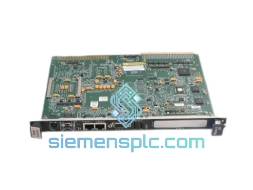
GE IS210MVRBH1A I/O Interface Board – Mark VIe Series
Mark VI
Origin US
I/O Interface Board
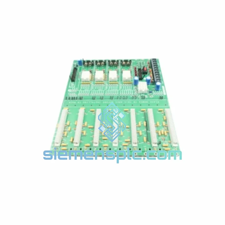
Request verified availability, condition, replacement risk review, packing options and courier lead time for DS200QTBDG1AAA.
Click Request Quote and the part number is inserted into the inquiry form automatically.
Core fields for model confirmation and RFQ routing. Detailed product narrative remains below.
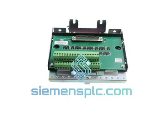
The DS200QTBDG1AAA is a discrete-signal termination board produced by General Electric for integration within the Mark VI turbine control platform. Its functional position in the control architecture is the physical and electrical boundary between field-side discrete devices — dry contacts, limit switches, proximity sensors, solenoid feedback circuits — and the deterministic logic layer executed by the Mark VI controller cards (VCMI, VCRC, VCCA). Every discrete input state transition that influences turbine sequencing, protection voting, or alarm annunciation must pass through this board’s signal conditioning chain before it is presented to the controller’s scan cycle.
The Mark VI system enforces a strict architectural separation between field wiring and control logic. Terminal boards handle all physical signal acquisition, wetting voltage distribution, and transient suppression. Controller cards handle all logic execution, redundancy voting, and communication. The DS200QTBDG1AAA’s role is therefore not passive — its electrical characteristics define the minimum detectable contact resistance, the maximum tolerable field-side transient energy, and the propagation delay budget available within the system’s 10 ms scan cycle. A board with degraded isolation resistance or elevated contact wetting voltage drop will introduce systematic errors into the voted discrete input data, with direct consequences for protection response accuracy.
In Triple Modular Redundant (TMR) Mark VI installations, three DS200QTBDG1AAA boards are deployed across the R, S, and T controller racks. Each board independently acquires the same field contact states and forwards digitized channel data to its associated VCMI card. The VCMI firmware executes a 2-of-3 majority vote on each discrete channel at every scan cycle. A single board failure or field wiring open-circuit on one rack produces a diagnostic flag in the HMI without interrupting turbine control, because the two remaining boards continue to supply consistent voted data. This architecture allows the DS200QTBDG1AAA to be replaced during a planned maintenance window without requiring a turbine shutdown, provided the replacement is executed within the system’s allowed single-fault exposure interval.
Real-time Stock & RFQ: [email protected] | WhatsApp: +86 18359268345
| Parameter | Specification |
|---|---|
| Part Number | DS200QTBDG1AAA |
| Manufacturer | General Electric (GE) |
| Platform | Mark VI Turbine Control System |
| Board Function | Discrete contact I/O field termination |
| Contact Wetting Voltage | 24 VDC nominal, regulated per terminal row |
| Logic HIGH Threshold | > 15 VDC |
| Logic LOW Threshold | < 5 VDC |
| Channel Isolation Voltage | 1,500 VAC per channel (optical isolation) |
| Isolation Architecture | Per-channel optocoupler — no shared isolation bus |
| Wetting Current Tolerance | Designed for field contact resistance up to 100 Ω |
| Transient Suppression | Per-channel TVS diode, inductive kickback rated |
| Terminal Block Type | Screw-clamp, cage-clamp compatible |
| Field Wire Range | 0.5 mm² to 2.5 mm² (AWG 20 – AWG 14) |
| Backplane Interface | Ribbon cable / direct backplane connector to VCMI/VCRC |
| Redundancy Support | TMR (R/S/T racks) and dual-redundant Mark VI configurations |
| Operating Temperature | 0°C to +60°C |
| Storage Temperature | -40°C to +85°C |
| Relative Humidity | 5% to 95% RH, non-condensing |
| PCB Protection | Acrylic conformal coating, IPC-A-610 Class 2 |
| Mounting Format | Mark VI panel enclosure, rack-mount PCB assembly |
| Regulatory Compliance | CE marked; RoHS-compatible; GE OEM specification |
| Country of Origin | United States |
| Warranty | 12 months from shipment date, manufacturing defects covered |
The DS200QTBDG1AAA implements a per-channel passive-active hybrid conditioning architecture. Each discrete input channel is routed through an independent optocoupler stage that provides galvanic separation rated at 1,500 VAC between the field terminal and the backplane signal path. This is a channel-by-channel isolation scheme — not a shared-bus arrangement — which means a fault condition on one field wire, including a sustained short to ground or a high-energy inductive transient from a solenoid coil collapse, cannot capacitively or conductively influence the isolation integrity of adjacent channels. In high-density turbine protection applications where dozens of discrete inputs share a single terminal board, this per-channel independence is a critical design requirement for maintaining voted input data integrity across all channels simultaneously.
Contact wetting is distributed from a regulated 24 VDC bus across the terminal rows. The wetting current is sized to reliably overcome contact resistance degradation in aged relay contacts — the design accommodates field contact resistance up to approximately 100 Ω while maintaining the logic HIGH threshold above 15 VDC at the optocoupler input. Each channel incorporates a series current-limiting resistor to prevent thermal overload of the terminal block assembly under sustained contact closure, and a transient voltage suppressor (TVS) diode rated to clamp inductive kickback events from solenoid coils and motor contactors below the optocoupler’s maximum forward voltage rating. This two-element protection scheme addresses both the steady-state thermal budget and the transient energy budget of the channel simultaneously.
The PCB layout enforces strict separation between the field-side signal return plane and the backplane digital ground. Analog reference planes are isolated from digital return paths, and the backplane connector pinout assigns dedicated shield grounds to prevent capacitive coupling between adjacent high-frequency digital signals and the low-level contact input channels. In turbine hall environments, broadband conducted and radiated EMC noise from variable-frequency drives, high-current bus bars, and arc flash events spans the 150 kHz to 30 MHz spectrum. The board’s ground architecture ensures that common-mode noise injected at the field terminal does not shift the logic threshold reference at the optocoupler input — preserving contact state resolution accuracy under worst-case EMC conditions without requiring external filtering hardware.
In TMR rack configurations, the three DS200QTBDG1AAA boards operate with fully independent power rails and signal buses. Each board’s optical isolators present a high-impedance input to the field wiring, so the parallel connection of three boards across the same field contact does not materially load the contact circuit or alter the wetting current distribution. The VCMI voting firmware resolves 2-of-3 agreement on each channel within the same scan cycle in which the input transition is detected — maintaining protection response latency within the system’s defined safety time budget without introducing inter-rack synchronization delays.
All DS200QTBDG1AAA units supplied through siemensplc.com are sourced as genuine General Electric OEM hardware. Each unit undergoes a structured pre-dispatch verification protocol: backplane connector pin continuity measurement across all positions, optical isolator forward-voltage check on every input channel, PCB visual inspection per IPC-A-610 Class 2 acceptance criteria, and ESD sensitivity verification per ANSI/ESD S20.20. Units that do not pass all checkpoints are quarantined and withheld from available inventory. No refurbished, aftermarket, or third-party equivalent boards are supplied under the DS200QTBDG1AAA part number.
Traceability documentation — including GE serial number, PCB revision level, and a certificate of conformance (CoC) — is available upon request for customers requiring incoming inspection records or regulatory audit trails. Units are packed in anti-static ESD shielding bags, cushioned within closed-cell foam inserts, and enclosed in double-wall corrugated export cartons fitted with shock-watch impact indicators. This packaging specification ensures that connector contacts and conformal coating arrive in the same verified condition as at dispatch, regardless of freight handling conditions.
Shipments are coordinated from Xiamen, China, with access to DHL Express, FedEx International Priority, and UPS Worldwide Expedited services. Indicative transit times: 2–4 business days to European industrial hubs, 3–5 business days to North American destinations, 1–3 business days to Southeast Asian facilities. Sea freight consolidation is available for bulk spare-parts procurement orders. Complete export documentation — commercial invoice, packing list, certificate of origin, and HS code declaration — is prepared for every international shipment to support customs clearance without delay at destination ports.
Email: [email protected]
WhatsApp: +86 18359268345
Web: siemensplc.com
Location: Xiamen, China
© 2026 siemensplc.com. All rights reserved.
We check the full part number, brand, series and visible nameplate information before quotation.
Sales confirms stock path, condition option, quantity and realistic lead time for export dispatch.
DHL, FedEx, UPS or buyer courier arrangements can be reviewed with packing requirements.
Similar brand or category products for fast comparison and multi-item RFQ lists.