GE
RFQ Ready
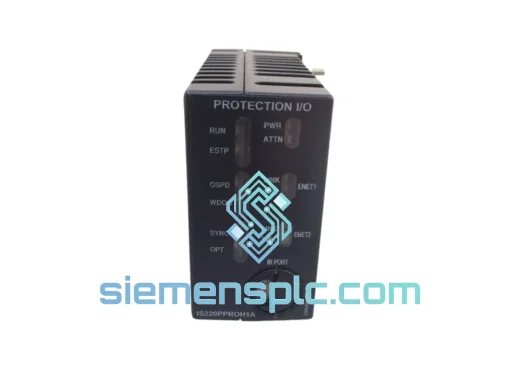
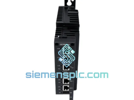
GE IS420UCSBH3A DCS Controller Module – Mark VIe
Mark VI
Origin US
DCS Controller Module
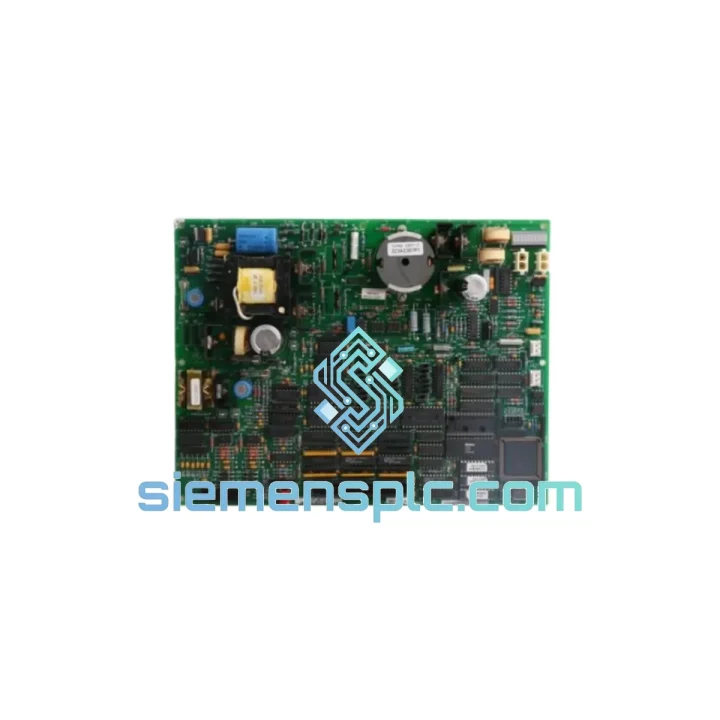
Request verified availability, condition, replacement risk review, packing options and courier lead time for DS200TCEAG1BFF.
Click Request Quote and the part number is inserted into the inquiry form automatically.
Core fields for model confirmation and RFQ routing. Detailed product narrative remains below.
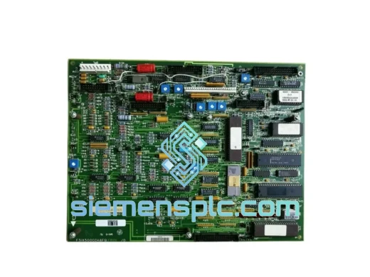
The DS200TCEAG1BFF is the dedicated Emergency Overspeed Protection (EOP) board within GE’s Mark VI Speedtronic turbine control platform. Its sole function is to provide a hardware-enforced, software-independent overspeed trip path for gas turbines, steam turbines, and combined-cycle drive trains. Unlike software-based protection layers that depend on CPU scan cycles, this board operates through discrete, latched relay logic that responds to shaft speed signals within a deterministic window — typically under 5 ms from threshold detection to contact output. This response characteristic is a direct consequence of the board’s analog comparator front-end, which bypasses the VCMI backplane arbitration entirely for the trip output path.
In a Mark VI architecture, the TCCA/TCCB/TCCC processor boards handle closed-loop control, sequencing, and diagnostics. The DS200TCEAG1BFF sits outside that TMR voting structure for the overspeed function specifically. This separation is intentional: IEC 61511 and API 670 both require that the final protective element for overspeed not share a common cause failure mode with the control system. The board accepts passive magnetic pickup (MPU) signals from the turbine shaft and processes them through independent frequency-to-voltage conversion circuits. Three independent comparator channels are implemented on-board, each with its own reference voltage trimmer, allowing field calibration of the trip setpoint without modifying firmware or control constants.
The board mounts in the Mark VI <R> or <P> controller rack and communicates board health status back to the VCMI via the IONet Ethernet segment. Diagnostic data — including comparator channel status, relay coil continuity, and power supply rail voltages — is surfaced in the ToolboxST HMI under the TCEA device tree. This means maintenance personnel can verify EOP board health during normal operation without interrupting the protection function, a capability that directly supports IEC 61511 proof-test interval requirements.
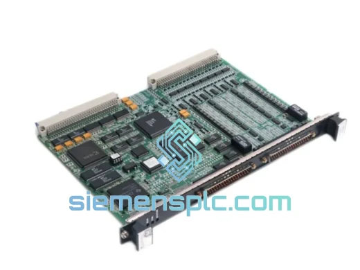
Physical construction uses a 6-layer PCB with ground-plane shielding between signal and power layers. Conformal coating is applied to the full board assembly, providing resistance to humidity, condensing moisture, and airborne particulates consistent with IEC 60068-2-78 damp heat testing. The board draws power from the Mark VI ±15 VDC and +5 VDC rails; onboard linear regulators provide local isolation for the analog comparator section, preventing digital switching noise from the backplane from coupling into the speed measurement circuits.
Real-time Stock & RFQ: [email protected] | WhatsApp: +86 18359268345
| Parameter | Specification |
|---|---|
| Part Number | DS200TCEAG1BFF |
| Manufacturer | GE (General Electric) |
| Platform | Mark VI Speedtronic Turbine Control System |
| Board Function | Emergency Overspeed Protection (EOP) |
| Speed Input Signal | Passive Magnetic Pickup (MPU), 1 Vrms – 50 Vrms |
| Input Frequency Range | 0 – 20,000 Hz |
| Comparator Channels | 3 independent channels with individual setpoint trimmers |
| Trip Response Time | <5 ms (threshold detection to relay contact output) |
| Output Relay Type | Latching relay, hardwired trip contact, Form C |
| Supply Voltage | ±15 VDC, +5 VDC from Mark VI rack power bus |
| Operating Temperature | 0°C to +60°C (ambient, forced-air cooled rack) |
| Humidity Tolerance | 5% – 95% RH non-condensing (conformal coated) |
| PCB Construction | 6-layer, FR4, full conformal coat per IEC 60068-2-78 |
| Communication Interface | IONet Ethernet (diagnostic status only, not trip path) |
| Rack Compatibility | Mark VI <R> and <P> controller racks |
| Firmware Dependency | None — trip path is fully hardware-implemented |
| Applicable Standards | IEC 61511, API 670, IEC 60068-2-78 |
| Condition Available | New OEM, Tested Surplus, Refurbished |
| Warranty | 12 months from date of shipment |
| Country of Origin | USA |
| Weight (approx.) | 980 g |
The DS200TCEAG1BFF implements a frequency-to-voltage (F/V) conversion front-end using a dedicated monolithic F/V converter IC per channel. Each channel’s output voltage is compared against a stable, temperature-compensated reference derived from a precision bandgap reference circuit. This architecture eliminates the drift that would otherwise occur with resistor-divider references over the board’s operating temperature range. The three comparator outputs feed into a 2-of-3 voting gate implemented in discrete TTL logic — not in a programmable device — which means the voting logic cannot be inadvertently modified by firmware updates or configuration changes.
EMC design follows a layered approach. The MPU input stage uses a differential line receiver with common-mode rejection ratio (CMRR) exceeding 60 dB at 10 kHz, which suppresses ground-loop noise common in turbine environments where shaft grounding currents can reach several amperes. Transient voltage suppressors (TVS diodes) rated at ±600 V are placed at the board edge connector on all signal inputs, providing protection against inductive kickback from the MPU cable during maintenance disconnection events.
The latching relay output circuit is powered from a dedicated, isolated DC/DC converter module on the board. This isolation ensures that a fault on the Mark VI main power bus — including a momentary dropout — does not inadvertently reset the trip latch. The relay coil is continuously monitored by a current-sense circuit; an open-coil condition is flagged as a diagnostic fault on IONet within one scan cycle of the VCMI, typically 10 ms. This coil monitoring capability is what allows the board to meet the diagnostic coverage requirements for SIL 2 classification under IEC 61511 without requiring redundant relay hardware.
The board revision suffix “G1BFF” encodes the hardware revision (G1), conformal coat specification (B), and connector variant (FF). Substituting a different revision suffix without consulting GE’s Mark VI hardware compatibility matrix can result in setpoint calibration offsets or IONet communication failures. When sourcing replacement boards, exact suffix matching is required for direct drop-in replacement.
Every DS200TCEAG1BFF unit shipped from our Xiamen facility undergoes a four-stage verification process before dispatch. Stage one is a visual inspection against GE’s published board artwork and component placement documentation, checking for counterfeit indicators including incorrect silkscreen fonts, non-OEM component markings, and solder joint anomalies inconsistent with wave-solder production. Stage two is a functional bench test using a Mark VI-compatible rack simulator: MPU signal injection at calibrated frequencies verifies comparator trip thresholds on all three channels, and relay output continuity is confirmed under load. Stage three cross-references the board’s firmware revision label and hardware suffix against GE’s Mark VI hardware compatibility matrix for the customer’s specific turbine application. Stage four is anti-counterfeit authentication using UV inspection and component date-code verification against known OEM production windows.
Units sourced as tested surplus carry a full 12-month warranty covering functional failure under normal operating conditions. New OEM units carry the original GE warranty terms. All units are packed in anti-static bags with foam-lined export cartons rated for air freight handling. Export documentation — including commercial invoice, packing list, and certificate of origin — is prepared for standard customs clearance in the EU, USA, Southeast Asia, and the Middle East. Typical air freight transit from Xiamen Gaoqi International Airport is 3–5 business days to major industrial hubs. DHL, FedEx, and UPS express accounts are maintained for time-critical shipments. For large-volume orders, sea freight consolidation from Xiamen Port is available with lead times quoted on request.
Email: [email protected]
WhatsApp: +86 18359268345
Web: siemensplc.com
Location: Xiamen, China
© 2026
We check the full part number, brand, series and visible nameplate information before quotation.
Sales confirms stock path, condition option, quantity and realistic lead time for export dispatch.
DHL, FedEx, UPS or buyer courier arrangements can be reviewed with packing requirements.
Similar brand or category products for fast comparison and multi-item RFQ lists.