GE Fanuc
RFQ Ready
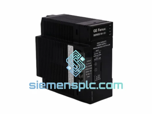
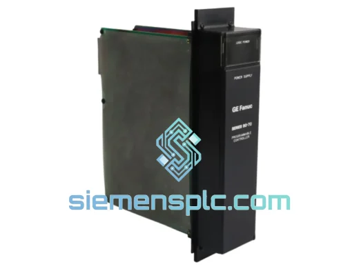
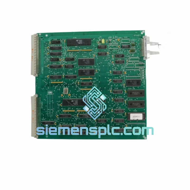
GE IC697PWR711 PLC Power Supply Module – Series 90-70
Fanuc
Origin US
PLC Power Supply Module
Request verified availability, condition, replacement risk review, packing options and courier lead time for G15PS4000.
Click Request Quote and the part number is inserted into the inquiry form automatically.
Core fields for model confirmation and RFQ routing. Detailed product narrative remains below.
The G15PS4000 is the primary power supply circuit board engineered for the GE Fanuc Series 15 CNC control platform — a high-performance numerical control system designed for multi-axis machining centers, large-bore turning mills, and precision contouring applications. Within the Series 15 cabinet architecture, this board occupies the foundational position in the power distribution hierarchy: it accepts mains AC input, performs rectification and regulation, and delivers stable, isolated DC voltage rails to every downstream subsystem — CPU, axis control, PMC, and operator panel I/O. Without a fully functional G15PS4000, the entire Series 15 control stack cannot achieve a valid power-good (PG) state, and the system will not enter operational mode.
This board is not a generic switching supply. It is a purpose-designed PCB assembly with rail-specific regulation circuits, sequenced startup logic, and hardware-level fault detection integrated directly into the GE Fanuc Series 15 backplane communication protocol. Each unit offered through siemensplc.com is sourced from verified industrial channels, subjected to multi-point electrical testing, and dispatched with full export documentation from Xiamen, China.
Real-time Stock & RFQ: [email protected] | WhatsApp: +86 18359268345
| Parameter | Specification |
|---|---|
| Part Number | G15PS4000 |
| Manufacturer | GE Fanuc (GE Intelligent Platforms) |
| Compatible Platform | GE Fanuc Series 15 CNC Control |
| Module Classification | Power Supply Circuit Board (PCB Assembly) |
| AC Input Voltage | 100–240 VAC, single-phase, universal input |
| Input Frequency | 50 / 60 Hz |
| DC Output Rails | +5 VDC (logic), ±12 VDC (analog/servo interface), +24 VDC (I/O field power) |
| Output Regulation | ±1% steady-state on all rails under rated load |
| Power-Good (PG) Signal | Open-collector logic output to Series 15 CPU; active-high on all rails within tolerance |
| Protection Circuits | Over-voltage, over-current, over-temperature, short-circuit on each rail |
| Operating Temperature | 0 °C to +55 °C (ambient, forced-air cabinet) |
| Storage Temperature | −20 °C to +70 °C |
| Relative Humidity | 5%–95% RH, non-condensing |
| Form Factor | PCB rack-mount assembly, Series 15 backplane-compatible |
| Weight | Approx. 700 g |
| Compliance | CE marked; RoHS-compatible materials |
| Warranty | 12 months — replacement against manufacturing defects or verified functional failure |
The G15PS4000 implements a multi-stage power conversion topology that separates the high-frequency switching section from the precision linear regulation stages used on the ±12 VDC analog rails. This architectural decision is deliberate: servo amplifier command signals and encoder feedback lines share the ±12 VDC rail with the Series 15 axis control boards. Any ripple or transient on this rail directly corrupts position feedback data, producing following-error alarms or, in worst cases, uncontrolled axis motion. The linear post-regulation stage on the ±12 VDC output suppresses switching noise to below 5 mV peak-to-peak — a specification that generic switching supplies cannot reliably meet.
The +5 VDC logic rail feeds the Series 15 CPU board (G15CPU), the PMC ladder logic processor, and the backplane data bus transceivers. This rail is regulated with a dedicated feedback loop independent of the other outputs, ensuring that CPU clock integrity is maintained even when the +24 VDC I/O field power rail experiences load transients from solenoid switching or relay coil energization — events common in machine tool environments.
EMC design on the G15PS4000 includes a common-mode choke on the AC input line, X- and Y-class capacitors across the line and from line to chassis ground, and a metal shield partition between the primary switching section and the secondary regulation section. This partition reduces capacitive coupling of high-frequency switching noise into the regulated output planes. The board’s ground plane layout uses a star-point topology, with the analog ground reference for the ±12 VDC rails isolated from the digital ground until a single controlled junction point — a standard technique for mixed-signal PCB design in industrial control hardware.
Startup sequencing is managed by a dedicated supervisory IC that monitors all rail voltages during power-on. The PG signal is asserted only after all rails have stabilized within their regulation windows for a minimum hold time (typically 50–100 ms). This prevents the Series 15 CPU from beginning its boot sequence on partially charged rails, which would otherwise cause non-deterministic initialization faults that are difficult to diagnose in the field.
Thermal management relies on the cabinet’s forced-air cooling path. The board’s power dissipation components — primarily the pass transistors on the linear regulation stages — are mounted with thermal interface material against the cabinet’s internal heatsink rail. Over-temperature protection triggers at approximately 85 °C junction temperature, asserting a fault signal to the CPU before thermal damage occurs.
Every G15PS4000 unit dispatched from siemensplc.com undergoes a structured pre-shipment verification protocol. Visual inspection covers PCB surface condition, solder joint integrity, electrolytic capacitor health (no bulging, no electrolyte leakage), and connector pin condition. Functional testing applies rated AC input and measures all DC output rails under load, verifying regulation accuracy and PG signal behavior. Units that do not meet OEM output specifications are quarantined and not offered for sale.
Logistics operations are based in Xiamen, China — a major export hub with direct access to DHL Express, FedEx International Priority, and UPS Worldwide Express services. Standard dispatch lead time for in-stock units is 1–2 business days after payment confirmation. International transit times are typically 3–5 business days to Europe, North America, Southeast Asia, and the Middle East via express courier. Full export documentation is provided with every shipment: commercial invoice, packing list, certificate of origin, and ESD handling instructions. Incoterms EXW Xiamen and CIF destination port are both available depending on buyer preference.
All units carry a 12-month warranty covering manufacturing defects and verified functional failure under normal operating conditions. Warranty claims are processed with a replacement-first policy — no extended RMA delays. Technical support from our engineering team is available via email and WhatsApp for installation guidance, compatibility verification, and fault diagnosis assistance.
Email: [email protected]
WhatsApp: +86 18359268345
Web: siemensplc.com
Location: Xiamen, China
© 2026 siemensplc.com. All rights reserved.
We check the full part number, brand, series and visible nameplate information before quotation.
Sales confirms stock path, condition option, quantity and realistic lead time for export dispatch.
DHL, FedEx, UPS or buyer courier arrangements can be reviewed with packing requirements.
Similar brand or category products for fast comparison and multi-item RFQ lists.