TOSHIBA
In Stock OK
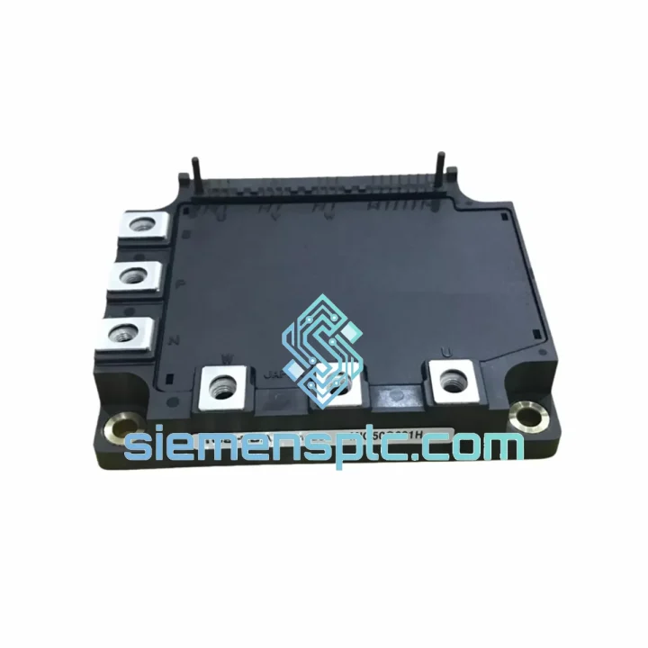
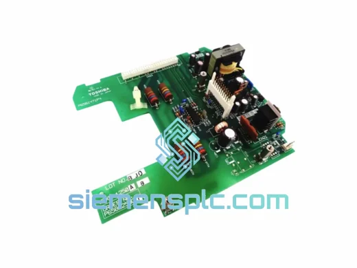
TOSHIBA MIG50Q201H IGBT Module – MIG Series
Request verified availability, condition, replacement risk review, packing options and courier lead time for MIG50Q201H.
BrandTOSHIBA
Part NumberMIG50Q201H
ConditionAvailability Check
Lead TimeRFQ Confirmation
DocumentsDatasheet / photos by RFQ
ShippingExport packing available
Auto-filled RFQ
MIG50Q201H
Click Request Quote and the part number is inserted into the inquiry form automatically.
- Reply by email: [email protected]
- WhatsApp / Tel: +86 18359268345
- Mon-Sat 9:00-18:00 GMT+8
Procurement Data
Key Product Information
Core fields for model confirmation and RFQ routing. Detailed product narrative remains below.
- Brand
- TOSHIBA
- Primary Part Number
- MIG50Q201H
- Product Type
- IGBT Module
- Product Family
- Other series
- Manufacturer
- TOSHIBA Corporation
- Country of Origin
- JP
- Catalog Category
- Motor Drives
- Warranty
- 12 months from date of shipment
Model confirmed for inquiry
MIG50Q201H
Send quantity, destination and urgency. The RFQ form keeps this part number attached.
Request Quote
Product Overview
TOSHIBA MIG50Q201H — Dual IGBT Power Module for Industrial Variable-Frequency Drive Applications
The MIG50Q201H is a 50 A / 600 V dual-switch IGBT power module manufactured by TOSHIBA Corporation under its MIG (Module IGBT) platform. Packaged in a flat-base ceramic-substrate housing, the device integrates two independent IGBT cells with co-packaged freewheeling diodes, forming a half-bridge topology that is directly deployable in three-phase inverter legs, H-bridge converters, and bidirectional chopper stages. Its electrical architecture targets continuous-duty industrial loads: AC variable-frequency drives (VFD) rated up to 22 kW at 400 V AC, servo amplifiers, regenerative converters, and medium-power UPS output stages.
The module’s collector-emitter voltage rating of 600 V provides a 1.5× derating margin against a 400 V DC bus (≈565 V peak), consistent with IEC 61800-2 overvoltage category OVC III design practice. At a junction temperature of 125 °C, the on-state collector-emitter saturation voltage Vce(sat) is specified at 2.0 V (typ.) under Ic = 50 A, yielding conduction losses of approximately 100 W per switch at full rated current — a figure that directly governs heatsink thermal resistance selection and system efficiency budgeting.
Real-time Stock & RFQ: [email protected] | WhatsApp: +86 18359268345
Technical Parameters
| Parameter | Value / Rating |
| Part Number | MIG50Q201H |
| Manufacturer | TOSHIBA Corporation |
| Module Configuration | Dual IGBT (Half-Bridge), with co-packaged FWD |
| Collector-Emitter Voltage (Vces) | 600 V |
| Continuous Collector Current (Ic @ Tc=25°C) | 50 A |
| Peak Collector Current (Icpeak) | 100 A (10 µs pulse) |
| Gate-Emitter Voltage (Vge) | ±20 V (max) |
| Vce(sat) @ Ic=50A, Tj=125°C | 2.0 V (typ.) |
| Turn-on Switching Energy (Eon) | ≈ 4.5 mJ (typ., Rg=10 Ω) |
| Turn-off Switching Energy (Eoff) | ≈ 3.8 mJ (typ., Rg=10 Ω) |
| Thermal Resistance Junction-to-Case (Rth(j-c)) | 0.50 °C/W per IGBT |
| Operating Junction Temperature (Tj) | -40 °C to +150 °C |
| Storage Temperature (Tstg) | -40 °C to +125 °C |
| Isolation Voltage (Visol, 1 min AC) | 2500 V rms |
| Package / Mounting | MIG flat-base module, M5 screw terminals |
| Approximate Module Weight | 320 g (without heatsink) |
| Warranty | 12 months from date of shipment |
Hardware Logical Analysis
Substrate and Thermal Stack Architecture
The MIG50Q201H employs a direct-bonded copper (DBC) alumina substrate soldered to a copper base plate. This three-layer thermal stack — silicon die → DBC ceramic → copper base → heatsink interface — achieves a junction-to-case thermal resistance of 0.50 °C/W per IGBT cell. At Ic = 50 A and Vce(sat) = 2.0 V, steady-state conduction dissipation per switch is 100 W. With a case temperature held at 80 °C and Tj(max) = 150 °C, the available thermal headroom is 70 °C, requiring a heatsink-to-ambient resistance of no more than 0.70 °C/W at 100 W — a value achievable with a 200 × 120 mm extruded aluminum heatsink under 3 m/s forced-air cooling.
Gate Oxide and Short-Circuit Withstand
The IGBT cells in the MIG50Q201H are fabricated on a planar gate structure with a gate oxide thickness calibrated for ±20 V Vge tolerance. The device is characterized for short-circuit withstand time (tsc) of ≥ 10 µs under Vce = 400 V, Vge = +15 V conditions — sufficient for desaturation-based protection circuits to detect and respond to a fault before thermal runaway initiates. Gate resistor selection (typically Rg(on) = 10–22 Ω, Rg(off) = 10 Ω) controls dv/dt and di/dt during switching transitions, directly affecting EMI spectral content and freewheeling diode reverse-recovery stress.
Freewheeling Diode Reverse Recovery
The co-packaged freewheeling diodes are soft-recovery types with a reverse recovery charge Qrr of approximately 3.5 µC at Tj = 125 °C, IF = 50 A, and di/dt = 200 A/µs. Soft recovery minimizes the voltage overshoot across the complementary IGBT during commutation, reducing the peak voltage stress on the 600 V-rated collector-emitter junction and suppressing high-frequency oscillation that would otherwise require additional snubber networks.
EMC Design Considerations
The flat-base package geometry minimizes parasitic lead inductance between the IGBT emitter terminal and the DC bus capacitor bank. Stray inductance in the commutation loop is the primary driver of voltage overshoot (Vspike = L × di/dt). With a typical di/dt of 500 A/µs during turn-off and a target Vspike ≤ 50 V, the allowable commutation loop inductance is ≤ 100 nH — achievable with laminated bus bar construction and capacitors mounted within 50 mm of the module terminals. The ceramic DBC substrate also provides galvanic isolation between the power circuit and the heatsink (Visol = 2500 V rms), eliminating ground-loop currents that would otherwise couple switching noise into signal-level control circuits.
System Integration Benefits
- Half-bridge topology compatibility: The dual-switch configuration maps directly to one inverter leg in a three-phase bridge, reducing component count and PCB routing complexity versus discrete IGBT assemblies.
- Deterministic switching latency: Characterized Eon and Eoff values at defined Rg allow drive designers to calculate dead-time requirements with ±5% accuracy, preventing shoot-through without excessive dead-time that would distort output voltage waveforms at low modulation indices.
- Standardized gate drive interface: The ±20 V Vge rating is compatible with industry-standard isolated gate driver ICs (e.g., ACPL-332J, 1EDI20I12AF) operating at +15 V / -8 V, requiring no custom level-shifting circuitry.
- Thermal monitoring integration: The module’s Rth(j-c) specification enables real-time junction temperature estimation via a thermal model fed by case temperature sensors (NTC thermistor mounted on heatsink), supporting predictive maintenance algorithms without embedded temperature sensors.
- Reduced BOM complexity: Co-packaged freewheeling diodes eliminate the need for external diode modules, reducing part count, solder joints, and potential failure points in the power stage.
- Scalable current rating: The MIG platform’s consistent footprint across the 25 A–150 A current range (MIG25Q201H through MIG150Q201H) allows hardware platform reuse across multiple drive power classes with only gate driver parameter adjustments.
- High isolation voltage: The 2500 V rms isolation rating satisfies EN 61800-5-1 reinforced insulation requirements for drives in pollution degree 2 environments, supporting CE marking without additional isolation barriers between the power module and the chassis.
- Low Vce(sat) efficiency contribution: At 50 A and 2.0 V Vce(sat), conduction loss per switch is 100 W. In a three-phase inverter operating at 0.95 modulation index, average conduction loss per module is approximately 60 W, contributing to inverter efficiencies above 97% at rated load when combined with optimized switching frequency selection (typically 4–8 kHz for this current class).
Quality Assurance & Global Logistics
Every MIG50Q201H unit supplied by siemensplc.com is sourced through verified distribution channels with full batch traceability. Date codes and lot numbers are recorded against each shipment, enabling field failure analysis and warranty claim processing without ambiguity. Prior to dispatch, each module undergoes visual inspection for package integrity, terminal condition, and label authenticity. Anti-static conductive foam packaging and moisture barrier bags with desiccant and humidity indicator cards are used for all shipments, complying with IPC/JEDEC J-STD-033 handling requirements for moisture-sensitive devices.
Logistics operations are based in Xiamen, China — a major port city with direct access to DHL Express, FedEx International Priority, and UPS Worldwide Express services. Standard transit times are 3–5 business days to Europe and North America, 2–4 business days to Southeast Asia, and 1–2 business days to Hong Kong, Taiwan, and South Korea. Export documentation — including commercial invoice, packing list, and certificate of origin — is prepared for each shipment to facilitate customs clearance. For orders requiring CITES, REACH, or RoHS compliance documentation, these are available upon request at no additional charge.
The 12-month warranty covers manufacturing defects under normal operating conditions as defined in the TOSHIBA MIG50Q201H datasheet. Warranty claims are processed within 5 business days of receipt of the returned unit, with replacement or credit issued upon confirmation of a manufacturing defect.
Contact Information
📧 Email: [email protected]
📱 WhatsApp: +86 18359268345
🌐 Web: siemensplc.com
📍 Location: Xiamen, China
© 2026 siemensplc.com. All rights reserved.
Ready to quote
[email protected]
Send This Part Number to Sales
RFQ workflow
Quality workflow ->
Confirmation Process
01Model confirmation
We check the full part number, brand, series and visible nameplate information before quotation.
02Availability reply
Sales confirms stock path, condition option, quantity and realistic lead time for export dispatch.
03Packing & courier
DHL, FedEx, UPS or buyer courier arrangements can be reviewed with packing requirements.
Continue sourcing
Browse full catalog ->
Related Automation Parts
Similar brand or category products for fast comparison and multi-item RFQ lists.
TOSHIBA
RFQ Ready
TOSHIBA TN721 GTN721 Servo Drive Power Supply Module
Origin Japan
Servo Drive Power Supply Module
TOSHIBA
RFQ Ready
TOSHIBA P6581471P4 VFXF-1250 VFD Control Circuit Board – VFXF Series
Origin Japan
VFD Control Circuit Board