Fuji Electric
RFQ Ready
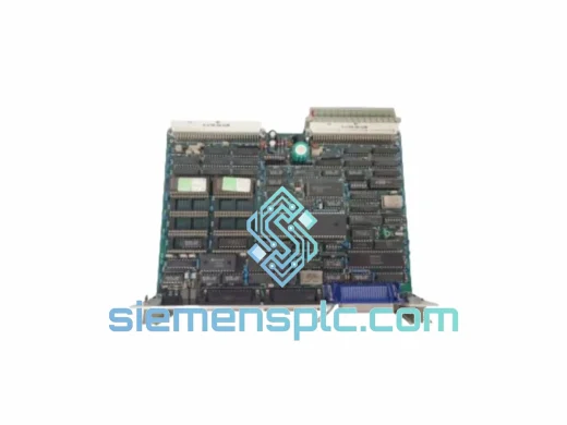
FUJI Electric EP-3531D C1-Z1 Inverter Control Board
P-3531D C1-Z1 FRENIC Series
Origin Japan
Inverter Drive Control Board
Request verified availability, condition, replacement risk review, packing options and courier lead time for SA537908-01.
Click Request Quote and the part number is inserted into the inquiry form automatically.
Core fields for model confirmation and RFQ routing. Detailed product narrative remains below.
The SA537908-01 is a two-wire, loop-powered differential pressure transmitter from FUJI Electric’s FCX-AII Series, designed for continuous process variable acquisition in DCS, SCADA, and safety-instrumented system (SIS) architectures. Its primary function within a control loop is to convert the differential pressure across a primary flow element — orifice plate, annubar, or venturi — into a calibrated 4–20 mA DC analog signal with superimposed HART 7 digital communication. The transmitter occupies the field instrument layer of the ISA-95 automation hierarchy, feeding real-time process data to the analog input (AI) card of the controller at a signal update rate of 100 ms, which is sufficient for all standard PID loop execution cycles in liquid, gas, and steam flow measurement.
The SA537908-01 variant is factory-configured for differential pressure service with a span rangeability of 100:1. This means a single installed instrument can be re-ranged across a 100-fold span without physical replacement — a significant operational advantage in batch processes where throughput targets change between production campaigns. The silicon resonant sensor at the core of this transmitter outputs a frequency-domain signal proportional to applied differential pressure. The onboard 24-bit sigma-delta A/D converter digitizes this frequency with a resolution of 0.01% of span, and the D/A output stage reconstructs the 4–20 mA signal with a total error band of ±0.1% of calibrated span under reference conditions (23°C ±2°C, 101.3 kPa). This error budget encompasses linearity, hysteresis, and repeatability — not merely static accuracy — making it directly applicable to loop uncertainty calculations per ISA-20 and IEC 60770-1.
In flow measurement applications, the transmitter’s square-root extraction function can be enabled locally, converting the differential pressure signal to a linear flow output without requiring the DCS to perform the extraction in software. This offloads computational burden from the controller and eliminates the signal discontinuity near zero flow that affects software-based extraction when the DP signal is noisy. The configurable low-flow cutoff (0–20% of span, in 1% increments) suppresses output noise below the minimum reliable measurement threshold, preventing false totalization in batch flow accounting systems.
Real-time Stock & RFQ: [email protected] | WhatsApp: +86 18359268345
| Parameter | Specification |
|---|---|
| Part Number / SKU | SA537908-01 |
| Manufacturer | FUJI Electric Co., Ltd. |
| Series | FCX-AII |
| Measurement Function | Differential Pressure (DP), Flow, Level |
| Output Signal | 4–20 mA DC, 2-wire; HART 7 superimposed |
| Sensor Technology | Silicon Resonant Sensor (frequency-output) |
| Total Error Band | ±0.1% of calibrated span (linearity + hysteresis + repeatability) |
| A/D Resolution | 24-bit sigma-delta |
| Rangeability (Turndown) | 100:1 |
| Measuring Range | 0–0.5 kPa to 0–500 kPa (span-configurable) |
| Static Pressure Limit | 21 MPa (3045 psi) |
| Process Temperature Range | -40°C to +120°C |
| Ambient Temperature Range | -40°C to +85°C |
| Supply Voltage | 10.5–42 V DC (HART mode: 12–42 V DC) |
| Maximum Loop Resistance | 1500 Ω at 24 V DC supply |
| Damping Adjustment | 0–32 s (0.1 s increments, configurable via HART) |
| Output Update Rate | 100 ms |
| Fail-Safe Output | 3.6 mA (low) or 21 mA (high), user-selectable |
| Wetted Materials | 316L stainless steel; Hastelloy C-276 diaphragm (optional) |
| Process Connection | 1/4-18 NPT or IEC 61518 coplanar flange |
| Electrical Entry | M20×1.5 or 1/2-14 NPT conduit |
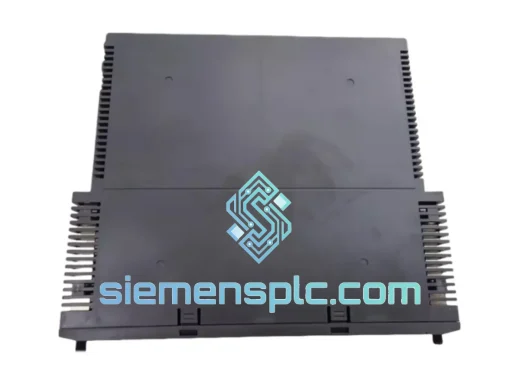
| Housing Material | Low-copper aluminum alloy (<0.4% Cu) |
| Ingress Protection | IP67 / NEMA 4X |
| Hazardous Area Certification | ATEX Ex ia IIC T4 Ga; IECEx; FM (Class I, Div. 1) |
| Functional Safety | SIL 2 capable (IEC 61508-2, HFT=0, SFF >90%) |
| Communication Protocol | HART 7 (optional: FOUNDATION Fieldbus H1, PROFIBUS PA) |
| EMC Compliance | IEC 61000-4-2 (8 kV ESD), IEC 61000-4-4 (2 kV EFT), IEC 61000-4-6 (10 V/m RF) |
| Quality Standard | ISO 9001:2015; 100% factory acceptance tested |
| Warranty | 12 months from date of shipment |
The SA537908-01 departs from conventional piezoresistive DP transmitter architecture in one fundamental respect: the primary sensing element outputs a frequency signal rather than a millivolt-level Wheatstone bridge voltage. A silicon resonant beam, microfabricated onto the sensor chip, changes its natural resonant frequency in direct proportion to the mechanical stress induced by differential pressure across the isolating diaphragm. This frequency is measured by the onboard ASIC using a precision oscillator reference with a stability of ±5 ppm/°C, and the resulting count is processed by the 24-bit sigma-delta converter. Because the primary measurement is frequency-based, the signal is immune to the gain-drift error that accumulates in amplified millivolt bridge circuits over temperature — the dominant error source in piezoresistive designs operating across wide ambient temperature ranges.
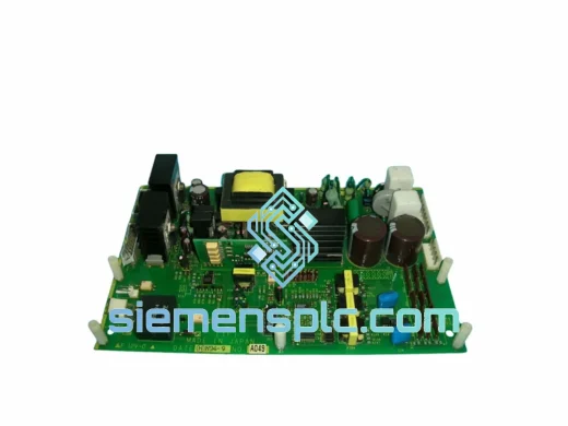
The electronics assembly uses a four-layer PCB with a continuous ground plane on layer 2, which provides a low-impedance return path for high-frequency interference currents and reduces the effective loop area of signal traces to below 1 cm². Ferrite bead filters (impedance: 600 Ω at 100 MHz) are placed in series on all I/O lines at the PCB boundary, and bidirectional TVS diodes rated at 600 W peak pulse power (10/1000 µs waveform) protect the signal terminals against surge transients from nearby lightning strikes or capacitor bank switching. This combination allows the transmitter to meet IEC 61000-4-5 surge immunity at 1 kV (line-to-line) and 2 kV (line-to-earth) without output deviation exceeding 0.1% of span — a critical requirement in outdoor installations where the field cable run may exceed 500 m.
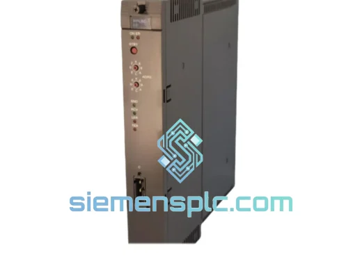
The dual-compartment housing separates the terminal block from the sensor electronics via a hermetic glass-to-metal feedthrough rated to IP67 independently of the terminal cover seal. The electronics cavity is factory-filled with dry nitrogen at 101 kPa gauge, creating an inert atmosphere that prevents oxidation of the resonant sensor element and the PCB surface finish over the 10-year design service life. The housing alloy’s copper content is held below 0.4% to satisfy ATEX Group IIC requirements for use in hydrogen atmospheres (Group IIC covers hydrogen, acetylene, and carbon disulfide — the most ignition-sensitive gas groups), without requiring the additional cost of stainless steel housings.
For SIL 2 loop applications, the transmitter’s internal diagnostic engine executes a 100 ms self-test cycle that checks sensor element resonant frequency against stored reference bounds, verifies A/D converter linearity using an internal reference voltage, and validates EEPROM configuration data via CRC-16 checksum. Any diagnostic failure drives the output to the configured fail-safe state within one 100 ms cycle — a response time that is deterministic and independent of the host system’s polling interval. The Safe Failure Fraction (SFF) exceeds 90%, and the Probability of Failure on Demand (PFD) for a 1oo1 voting architecture with a 12-month proof test interval is documented in the FUJI Electric SIL data sheet, enabling direct use in IEC 61511 safety requirement specification (SRS) calculations.
Each SA537908-01 unit available through siemensplc.com is sourced with full supply chain traceability. FUJI Electric’s manufacturing operations for the FCX-AII Series are conducted under ISO 9001:2015 certification, and every transmitter undergoes a mandatory factory acceptance test (FAT) protocol before shipment. The FAT sequence includes hydrostatic pressure testing at 1.5× maximum working pressure (31.5 MPa for the standard body), five-point calibration verification across 0%, 25%, 50%, 75%, and 100% of span, HART 7 communication functional test, and fail-safe output verification at both the low (3.6 mA) and high (21 mA) configured states. A factory test report documenting the as-found and as-left calibration data accompanies each unit.
Our logistics operations are based in Xiamen, Fujian Province, China — a city with direct access to Xiamen Gaoqi International Airport (IATA: XMN), one of China’s top-ten cargo airports by throughput volume, and Xiamen Port, a major container terminal with weekly direct services to Rotterdam, Los Angeles, Dubai, and Singapore. For in-stock units, standard dispatch lead time is 1–3 business days from order confirmation. Express dispatch (same-day for orders confirmed before 14:00 CST) is available for project-critical requirements. Supported carriers include DHL Express, FedEx International Priority, UPS Worldwide Express, and TNT Economy Express for cost-sensitive shipments. Volume orders are eligible for air freight consolidation with weekly departures. Each shipment is accompanied by a commercial invoice, packing list, certificate of origin (Form E for ASEAN preferential tariff), and the FUJI Electric factory test report. Export classification is HS Code 9026.20 (instruments for measuring or checking pressure of liquids or gases), with EAR99 designation applicable to most destination countries, simplifying export licensing for the majority of global destinations.
The 12-month warranty from date of shipment covers manufacturing defects and functional failures under normal operating conditions as defined in FUJI Electric’s standard warranty terms. Warranty claims are acknowledged within 2 business days, with advance replacement units dispatched for critical process applications to minimize unplanned downtime. Post-warranty technical support, including calibration guidance and spare parts sourcing, is available through our engineering team.
Email: [email protected]
WhatsApp: +86 18359268345
Web: siemensplc.com
Location: Xiamen, China
© 2026 siemensplc.com. All rights reserved.
We check the full part number, brand, series and visible nameplate information before quotation.
Sales confirms stock path, condition option, quantity and realistic lead time for export dispatch.
DHL, FedEx, UPS or buyer courier arrangements can be reviewed with packing requirements.
Similar brand or category products for fast comparison and multi-item RFQ lists.