BOSCH Rexroth
RFQ Ready
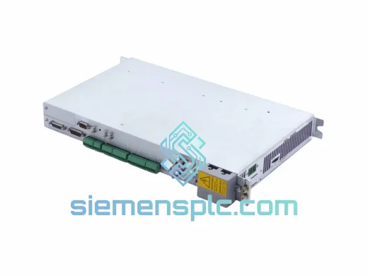
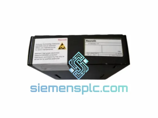
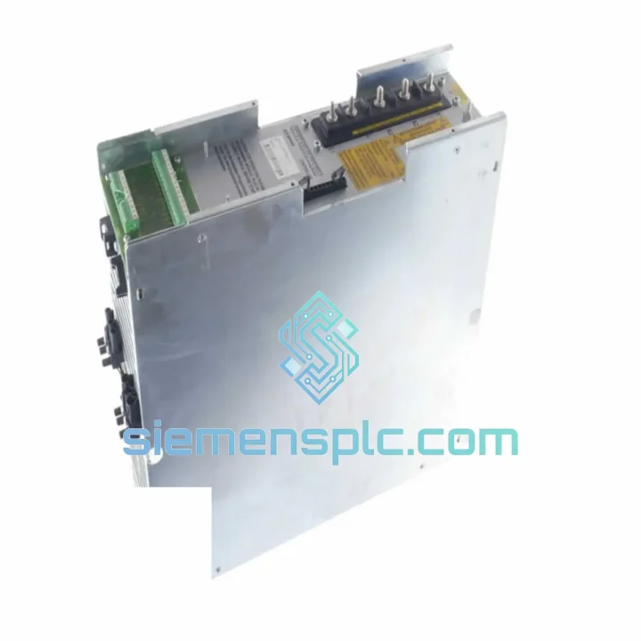
Rexroth VT5035-17 Proportional Amplifier Card – VT5035 Series
VT5035 Series
Origin DE
Proportional Amplifier Card
Request verified availability, condition, replacement risk review, packing options and courier lead time for 1-030-300-W1.
Click Request Quote and the part number is inserted into the inquiry form automatically.
Core fields for model confirmation and RFQ routing. Detailed product narrative remains below.
The Rexroth TDM2.1-030-300-W1 is a transistor-based AC servo drive module belonging to Bosch Rexroth’s DIAX02 modular drive family. Within a closed-loop servo axis, this unit occupies the power conversion and current regulation layer: it accepts a DC bus voltage from a shared supply module (TVD, TVM, or KDV series), synthesizes a three-phase PWM output to the servo motor, and closes the current control loop at a cycle time determined by the firmware variant loaded. The “030” designator specifies a 30 A continuous output rating; the “300” designator specifies the peak current envelope available for acceleration transients. The “W1” suffix identifies the internal forced-air cooling configuration, meaning the drive integrates its own fan assembly and does not rely on external cabinet airflow for thermal management.
In a multi-axis DIAX02 rack, the TDM2.1-030-300-W1 connects to the DC bus via the module’s internal bus bar, shares regenerative braking capacity with adjacent drives through the common bus, and communicates with the CNC or motion controller via SERCOS fiber-optic ring or analog/digital interface depending on the firmware variant (FWA-DIAX02-xxx). The module’s position in the control loop is strictly subordinate to the higher-level position controller — it executes torque and velocity commands with a current loop bandwidth that, in DIAX02 hardware, is fixed by the IGBT switching frequency and the current regulator gain tables stored in the drive’s non-volatile parameter memory.
This architecture makes the TDM2.1-030-300-W1 particularly suited to applications where axis-level current regulation must be deterministic and independent of the fieldbus scan cycle — a requirement common in CNC machining centers, servo press axes, and injection molding clamp drives where torque ripple directly affects surface finish or part dimensional accuracy.
Real-time Stock & RFQ: [email protected] | WhatsApp: +86 18359268345
| Parameter | Value / Specification |
|---|---|
| Part Number | TDM2.1-030-300-W1 |
| Manufacturer | Bosch Rexroth |
| Series | DIAX02 — TDM (Transistor Drive Module) |
| Continuous Output Current | 30 A (RMS, per phase) |
| Peak Output Current | 300 A (short-duration transient, firmware-limited) |
| DC Bus Input Voltage | Derived from supply module; nominal 540 VDC (from 3-phase 400 VAC input) |
| Supply Voltage (mains, via supply module) | 3-phase AC 200–480 V ±10%, 50/60 Hz |
| Control Voltage | 24 VDC (logic and fan supply, from supply module) |
| Switching Frequency (IGBT) | 4 kHz / 8 kHz (firmware-selectable) |
| Current Loop Cycle Time | 62.5 µs (at 8 kHz switching) |
| Feedback Interfaces | Resolver; EnDat 2.1 / 2.2; Hiperface; TTL incremental encoder |
| Command Interface | SERCOS I fiber-optic ring; ±10 V analog; digital I/O (firmware-dependent) |
| Motor Compatibility | Rexroth MKD, MHD, MKE, 2AD series; third-party motors with matching feedback |
| Compatible Supply Modules | TVD1.3, TVM1.2, KDV1.3, KDV2.2 |
| Cooling Method | Internal forced-air fan (W1 suffix) |
| Protection Class | IP20 |
| Mounting Orientation | Vertical, DIN rail or panel mount within DIAX02 rack |
| Ambient Operating Temperature | 0 °C to +45 °C (derate above 40 °C) |
| Storage Temperature | -25 °C to +70 °C |
| Relative Humidity | 5–95%, non-condensing |
| Approx. Weight | ~2 kg |
| Certifications | CE; UL (region-dependent) |
| Warranty | 12 months from date of shipment |
The TDM2.1-030-300-W1’s power stage is built around a three-phase IGBT bridge with gate drive circuits that implement desaturation detection — a hardware-level short-circuit protection mechanism that monitors collector-emitter voltage during the on-state and triggers a controlled shutdown within microseconds if a fault condition is detected. This is distinct from software overcurrent protection and operates independently of the firmware execution cycle, providing a first line of defense against motor winding faults or cable insulation failures.
The DC bus interface includes a pre-charge circuit that limits inrush current during power-up, preventing voltage collapse on the shared bus when multiple TDM modules are energized simultaneously. This is particularly relevant in multi-axis racks where five or more drives share a single TVD or KDV supply: without coordinated pre-charge, the combined capacitor bank of all drives would draw a current spike sufficient to trip the supply module’s overcurrent protection.
EMC design in the TDM2.1 series addresses both conducted and radiated emissions. The internal DC bus filter capacitors are physically distributed across the module’s PCB to minimize loop inductance in the high-frequency switching path, reducing common-mode noise injection into the DC bus. The motor output terminals are designed for use with shielded motor cables; the shield termination point at the drive end is connected to the module’s PE (protective earth) rail, which is bonded to the cabinet backplate. This 360° shield termination at both motor and drive ends is the primary mechanism for suppressing radiated emissions from the motor cable — a cable that, at 8 kHz switching frequency, acts as an antenna for frequencies up to several hundred kilohertz.
The feedback interface circuitry includes differential line receivers for all digital encoder signals, providing common-mode rejection of noise induced by the motor cable’s proximity. For resolver feedback, the excitation signal is generated by a dedicated oscillator within the drive, and the resolver-to-digital conversion is performed by a dedicated ASIC that outputs position data to the current regulator at the full 62.5 µs cycle rate — there is no additional latency from a separate feedback processor.
Parameter storage uses non-volatile EEPROM within the drive module. Motor-specific data (current limits, feedback type, pole pair count, thermal model coefficients) is stored as a parameter set that can be backed up via the IndraWorks engineering tool or the BTV04 operator panel. This means a replacement TDM2.1-030-300-W1 can be pre-loaded with the parameter set from the failed unit before installation, reducing axis re-commissioning to a parameter download and a brief functional test rather than a full re-tuning procedure.
Every TDM2.1-030-300-W1 unit supplied by siemensplc.com is sourced as genuine Bosch Rexroth original hardware. Units are not rebranded, remanufactured under third-party labels, or assembled from non-OEM components. Before shipment, each unit undergoes a structured inspection protocol: visual examination of the PCB, connector housings, and IGBT module for physical damage; power-on functional test confirming DC bus pre-charge, fan operation, and firmware boot sequence; and parameter verification confirming the firmware variant code matches the part number designation.
Units are shipped from our warehouse in Xiamen, China — a logistics hub with direct access to DHL Express, FedEx International Priority, and UPS Worldwide Expedited services. Standard export documentation (commercial invoice, packing list, certificate of origin) is prepared for all international shipments. For customers in the EU, a EUR.1 movement certificate can be provided where applicable. For customers requiring air freight with dangerous goods compliance (lithium battery exclusion confirmation), we provide the relevant IATA documentation.
Transit times from Xiamen to major industrial regions: Western Europe 3–5 business days (DHL Express); North America 3–5 business days (FedEx IP); Southeast Asia 2–3 business days; Middle East 4–6 business days. Sea freight consolidation is available for bulk orders of 10+ units. All shipments are covered by cargo insurance. The 12-month warranty covers defects in materials and workmanship under normal operating conditions as defined in the Rexroth product documentation; warranty claims are processed with a target response time of 48 hours from receipt of the defective unit.
Email: [email protected]
WhatsApp: +86 18359268345
Web: siemensplc.com
Location: Xiamen, China
© 2026 siemensplc.com. All rights reserved.
We check the full part number, brand, series and visible nameplate information before quotation.
Sales confirms stock path, condition option, quantity and realistic lead time for export dispatch.
DHL, FedEx, UPS or buyer courier arrangements can be reviewed with packing requirements.
Similar brand or category products for fast comparison and multi-item RFQ lists.