Vibro-Meter
RFQ Ready
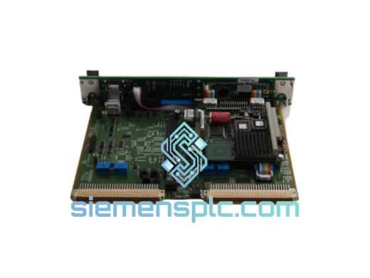
VIBRO-METER VM600 CPU M 200-595-100-032 CPU Module
Origin Switzerland
PLC & DCS CPU Module
Request verified availability, condition, replacement risk review, packing options and courier lead time for 204-682-000-061S.
Click Request Quote and the part number is inserted into the inquiry form automatically.
Core fields for model confirmation and RFQ routing. Detailed product narrative remains below.
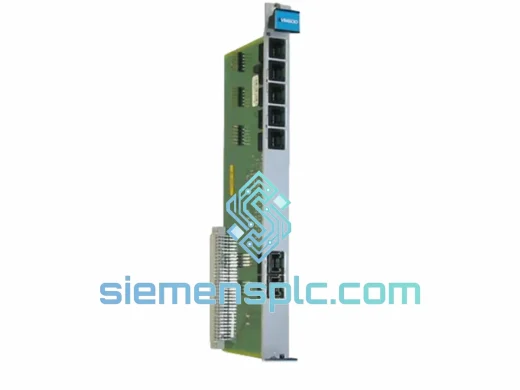
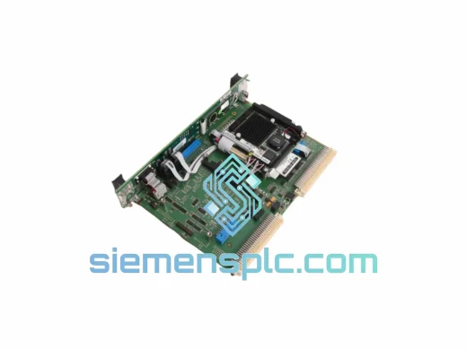
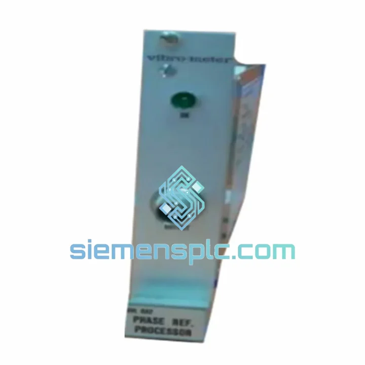
The VIBRO METER UVL682, identified by part number 204-682-000-061S, is a dedicated vibration signal conditioning and processing module engineered for continuous machinery protection in rotating equipment applications. Manufactured by Meggitt’s VIBRO METER division in Switzerland, this unit occupies a defined slot within the CM series modular rack architecture and performs real-time signal acquisition, RMS/peak conversion, alarm threshold comparison, and relay trip output — all within a single, field-replaceable card format.
In a typical API 670-compliant protection loop, the UVL682 sits between the field transducer (velocity sensor, accelerometer, or eddy-current proximity probe driver) and the plant DCS or safety PLC. Its function is deterministic: accept a raw vibration signal, condition it against configurable setpoints, and assert discrete relay contacts or a 4–20 mA analog output to the upstream control layer. This architecture ensures that machinery protection logic is executed at the module level, independent of DCS scan cycle latency — a critical requirement for turbine and compressor protection where trip response times must remain below 100 ms.
The 061S suffix in the part number 204-682-000-061S denotes a specific factory configuration variant within the UVL682 product family. Buyers should cross-reference this suffix against the OEM configuration matrix to confirm input transducer type compatibility (velocity vs. acceleration vs. proximity) before installation. siemensplc.com maintains technical documentation and can provide the relevant VIBRO METER datasheet upon request.
Real-time Stock & RFQ: [email protected] | WhatsApp: +86 18359268345
| Parameter | Specification |
|---|---|
| Manufacturer | VIBRO METER (Meggitt SA, Switzerland) |
| Model Number | UVL682 |
| Full Part Number | 204-682-000-061S |
| Module Series | CM Series Modular Rack |
| Primary Function | Vibration signal conditioning, RMS/peak processing, alarm & trip relay output |
| Accepted Input Signal Types | Velocity (ICP/IEPE), Acceleration, or Eddy-current proximity (suffix-dependent) |
| Analog Output | 4–20 mA, proportional to vibration amplitude |
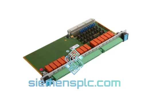
| Relay Outputs | Alert (Alarm) relay + Danger (Trip) relay, configurable setpoints |
| Supply Voltage | 24 VDC nominal (from rack backplane PSU) |
| Power Consumption | ≤ 3 W (typical, module-level) |
| Operating Temperature | −20 °C to +70 °C |
| Storage Temperature | −40 °C to +85 °C |
| Relative Humidity | 5–95 % RH, non-condensing |
| Mounting Format | Plug-in card, VIBRO METER CM series 19″ rack chassis |
| Connector Interface | Rear-panel DIN41612 or equivalent rack backplane connector |
| Compliance Standards | API 670 (5th Ed.), IEC 61511, CE (EMC + LVD), ISO 10816 / ISO 20816 |
| Country of Origin | Switzerland |
| Module Weight | Approx. 500 g |
| Warranty | 12 months from date of shipment (siemensplc.com standard) |
The UVL682 implements a layered signal processing chain that begins at the front-end input stage and terminates at the relay driver and analog output buffer. Understanding this chain is essential for system integrators specifying the module in SIL-assessed protection loops.
Input Stage & Transducer Excitation: Depending on the 061S configuration, the input stage provides either a constant-current excitation source for ICP/IEPE-type accelerometers or a bias voltage supply for eddy-current proximity probe drivers. The input impedance is matched to the transducer output impedance to minimize signal reflection and maximize dynamic range across the full measurement bandwidth. A hardware-level open-circuit and short-circuit detection circuit monitors transducer health continuously; a fault condition asserts a dedicated relay output independent of the vibration alarm logic, ensuring that a failed sensor does not silently disable the protection loop.
Anti-Aliasing Filter & Signal Conditioning: The raw transducer signal passes through a hardware anti-aliasing low-pass filter before any digital conversion. The filter cutoff frequency is selected to match the measurement bandwidth of the configured transducer type, suppressing out-of-band noise that would otherwise corrupt RMS calculations. This is a passive analog filter stage — not a software-configurable DSP filter — which means its frequency response is deterministic and not subject to firmware revision changes.
RMS / Peak Detection: The UVL682 performs true RMS computation using an analog RMS-to-DC converter circuit, not a software approximation. True RMS measurement is mandatory for velocity-type vibration signals where the waveform is non-sinusoidal (e.g., bearing defect frequencies superimposed on shaft rotation harmonics). The peak detector circuit operates in parallel, allowing simultaneous RMS and peak amplitude monitoring without multiplexing delays.
Setpoint Comparison & Relay Logic: Alert and Danger setpoints are configured via front-panel potentiometers or internal DIP switches (model-dependent). The comparator circuit is implemented in hardware logic, not firmware, which eliminates the possibility of a software fault masking a genuine vibration exceedance. Relay contact ratings are specified for the inductive loads typical of solenoid valve and shutdown actuator circuits, with arc suppression components integrated on the PCB.
EMC Design: The module PCB incorporates ground plane partitioning to isolate the analog signal processing section from the relay driver section. Relay coil transients are suppressed by flyback diodes rated for the full relay coil energy. The rack chassis provides a Faraday cage enclosure, and the backplane connector includes chassis ground pins that bond the module to the rack frame, providing a low-impedance return path for common-mode interference currents. This design approach meets the conducted and radiated emission limits of EN 55011 Class A and the immunity requirements of IEC 61000-4-2 through IEC 61000-4-6.
Galvanic Isolation: The 4–20 mA analog output is galvanically isolated from the input signal ground and the relay common, preventing ground loop currents from introducing measurement errors in DCS input cards that share a common analog ground bus. Isolation voltage is rated to withstand the transient overvoltages typical of industrial power distribution environments.
Every VIBRO METER UVL682 204-682-000-061S unit dispatched by siemensplc.com is sourced from verified supply channels with full part number and serial number traceability. Prior to shipment, each module undergoes a structured pre-dispatch inspection protocol:
Logistics operations are based in Xiamen, China. Standard international shipment is via DHL Express or FedEx International Priority, with typical transit times of 3–7 business days to major industrial hubs in Europe, the Middle East, Southeast Asia, and the Americas. Sea freight consolidation is available for bulk orders. All shipments are fully tracked and insured.
Email: [email protected]
WhatsApp: +86 18359268345
Web: siemensplc.com
Location: Xiamen, China
© 2026 siemensplc.com. All rights reserved.
We check the full part number, brand, series and visible nameplate information before quotation.
Sales confirms stock path, condition option, quantity and realistic lead time for export dispatch.
DHL, FedEx, UPS or buyer courier arrangements can be reviewed with packing requirements.
Similar brand or category products for fast comparison and multi-item RFQ lists.