Yaskawa
In Stock OK
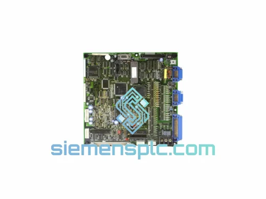
YASKAWA YPCT11065-1-4 Inverter Control Board – G7 F7 E7 Series
Request verified availability, condition, replacement risk review, packing options and courier lead time for YPCT11065-1-4.
BrandYaskawa
Part NumberYPCT11065-1-4
ConditionAvailability Check
Lead TimeRFQ Confirmation
DocumentsDatasheet / photos by RFQ
ShippingExport packing available
Auto-filled RFQ
YPCT11065-1-4
Click Request Quote and the part number is inserted into the inquiry form automatically.
- Reply by email: [email protected]
- WhatsApp / Tel: +86 18359268345
- Mon-Sat 9:00-18:00 GMT+8
Procurement Data
Key Product Information
Core fields for model confirmation and RFQ routing. Detailed product narrative remains below.
- Brand
- Yaskawa
- Primary Part Number
- YPCT11065-1-4
- Product Type
- Inverter Control Board
- Series / Family
- G7 F7 E7
- Manufacturer
- YASKAWA Electric Corporation
- Country of Origin
- JP
- Catalog Category
- Motor Drives
- Operating Temp.
- -10 °C to +50 °C (ambient, per G7/F7/E7 drive enclosure spec)
- Humidity
- 5 % to 95 % RH, non-condensing
- Warranty
- 12 months from dispatch date
Model confirmed for inquiry
YPCT11065-1-4
Send quantity, destination and urgency. The RFQ form keeps this part number attached.
Request Quote
Product Overview
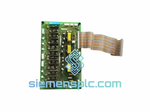
YASKAWA YPCT11065-1-4 — Gate Drive Control Board for G7 / F7 / E7 Series Variable Frequency Drives
The YASKAWA YPCT11065-1-4 is the dedicated inverter gate drive and signal processing PCB installed in YASKAWA’s G7, F7, and E7 series variable frequency drives. Within the drive’s power conversion architecture, this board occupies the critical interface layer between the DSP-based main control unit and the IGBT power module. It receives PWM switching commands from the CPU board, conditions and isolates those signals through optocoupler arrays, and delivers precisely timed gate pulses to each of the six IGBT switches in the three-phase bridge. Any timing deviation at this stage directly affects output voltage waveform quality, motor torque linearity, and thermal distribution across the power stack. The YPCT11065-1-4 is therefore not a peripheral component — it is a deterministic element in the drive’s closed-loop vector control chain.
The board carries hardware revision suffix “-1-4”, which denotes a specific PCB layout generation. Revision-level differences in YASKAWA drive boards typically involve gate resistor values, bootstrap capacitor ratings, or optocoupler model substitutions that affect switching rise/fall times. Substituting a mismatched revision can introduce asymmetric dead-time behavior across the bridge arms, leading to DC bus ripple, increased EMI emissions, or nuisance overcurrent faults (OC1/OC2/OC3). Procurement teams and field engineers must match the revision suffix precisely to the installed drive’s existing board label before ordering.
This listing covers a genuine OEM YPCT11065-1-4 sourced through verified YASKAWA distribution channels, inspected prior to dispatch, and shipped from Xiamen, China via DHL Express, FedEx International Priority, or UPS Worldwide Expedited — with full tracking and commercial invoice documentation for customs clearance.
Real-time Stock & RFQ: [email protected] | WhatsApp: +86 18359268345
Technical Parameters
| Parameter | Specification |
|---|---|
| Part Number (MPN) | YPCT11065-1-4 |
| Manufacturer | YASKAWA Electric Corporation |
| Component Classification | Inverter Gate Drive & Control Signal PCB |
| Compatible Drive Series | YASKAWA G7, F7, E7 Series VFD |
| Voltage Class Compatibility | 200 V class / 400 V class (confirm per drive nameplate) |
| Primary Function | PWM signal isolation, IGBT gate drive, fault signal feedback |
| Isolation Technology | Optocoupler-based galvanic isolation per gate channel |
| Hardware Revision | -1-4 (must match installed board label) |
| PCB Condition | New, genuine OEM — no refurbished or remanufactured stock |
| Connector Interface | Multi-pin ribbon and discrete wire harness (drive-specific) |
| Operating Temperature | -10 °C to +50 °C (ambient, per G7/F7/E7 drive enclosure spec) |
| Storage Temperature | -20 °C to +65 °C |
| Humidity | 5 % to 95 % RH, non-condensing |
| Weight (with packaging) | 4.46 kg |
| Warranty | 12 months from dispatch date |
| Shipping Origin | Xiamen, China |
| Logistics Partners | DHL Express / FedEx International / UPS Worldwide |
Hardware Logical Analysis
The YPCT11065-1-4 implements a six-channel isolated gate drive topology corresponding to the upper and lower switches of each phase leg (U, V, W) in the three-phase IGBT bridge. Each channel uses a dedicated optocoupler — typically a high-speed device with a propagation delay in the sub-microsecond range — to transfer the PWM command signal across the isolation barrier without introducing phase skew between channels. This symmetry is essential: any inter-channel propagation mismatch beyond the drive’s dead-time compensation window will cause shoot-through risk or uneven thermal loading across the IGBT module.
The board also integrates the bootstrap power supply circuitry for the high-side gate drivers. Bootstrap capacitors are charged during the low-side switch conduction interval and must sustain sufficient voltage to fully enhance the high-side IGBT gate during the subsequent switching cycle. The capacitor selection on the -1-4 revision is matched to the switching frequency range of the G7/F7/E7 platform (typically 2 kHz to 15 kHz carrier frequency), ensuring adequate gate enhancement across the full modulation index range.
EMC design on the YPCT11065-1-4 follows YASKAWA’s standard practice for industrial drive PCBs: the gate drive traces are routed with controlled impedance and minimal loop area to reduce radiated emissions from the high dV/dt switching transients. Ground plane segmentation separates the low-voltage signal domain from the gate drive power domain, with a single-point connection to minimize circulating ground currents. Ferrite bead filtering is applied at the board’s power input to attenuate conducted noise from the DC bus. These measures collectively support compliance with IEC 61800-3 Category C2 EMC requirements applicable to the G7/F7/E7 drive family.
Fault detection circuitry on the board monitors desaturation conditions on each IGBT channel. If a switch fails to fully turn on — due to gate voltage collapse, device degradation, or excessive collector current — the desaturation comparator pulls the gate low within microseconds and asserts a fault signal back to the main CPU board, triggering an OC (overcurrent) or GF (ground fault) protective trip. This hardware-level protection operates independently of the firmware control loop, providing a deterministic safety response that does not depend on software scan cycle timing.
System Integration Benefits
- Deterministic PWM Fidelity: Matched optocoupler propagation delays across all six gate channels preserve the CPU-generated dead-time intervals, preventing cross-conduction events and maintaining output voltage THD within drive specification.
- Thermal Symmetry Across the Bridge: Uniform gate drive strength ensures equal switching losses in each IGBT, distributing heat evenly across the power module and extending IGBT service life under cyclic load profiles.
- Hardware-Level Overcurrent Protection: Desaturation detection operates at the gate drive layer, independent of firmware, providing sub-microsecond fault response that protects the IGBT module from catastrophic failure during load transients or short-circuit events.
- Galvanic Isolation Integrity: Optocoupler isolation between the control signal domain and the gate drive power domain prevents ground loop currents from corrupting PWM timing signals, which is particularly important in installations with long motor cables or poor PE bonding.
- Bootstrap Supply Stability: Correctly rated bootstrap capacitors maintain high-side gate drive voltage across the full carrier frequency range (2–15 kHz), ensuring consistent IGBT gate enhancement without requiring external isolated power supplies for the high-side drivers.
- EMC Compliance Support: PCB-level EMC design (controlled impedance routing, ground plane segmentation, ferrite filtering) reduces conducted and radiated emissions from the gate drive stage, supporting system-level compliance with IEC 61800-3 without additional external filtering.
- Plug-Compatible Replacement: The YPCT11065-1-4 is a direct OEM replacement for the same revision board in G7/F7/E7 drives. No firmware modification, parameter re-initialization, or mechanical adaptation is required — reducing mean time to repair (MTTR) in field service scenarios.
- Diagnostic Transparency: Fault signals generated at the gate drive board are mapped to specific drive fault codes (OC1, OC2, OC3, GF) visible on the drive’s operator panel, enabling maintenance personnel to isolate faults to the gate drive layer without oscilloscope-level diagnostics.
- Long-Term Parts Availability: Sourced through verified YASKAWA distribution with full lot traceability, ensuring the board’s component BOM matches the original factory specification — critical for installations requiring documented maintenance records under ISO 9001 or functional safety frameworks.
Quality Assurance & Global Logistics
Every YPCT11065-1-4 unit dispatched from our Xiamen facility undergoes a structured pre-shipment inspection protocol. Visual examination checks for physical damage, solder joint integrity, component seating, and counterfeit markers (including UV ink verification on YASKAWA-marked ICs). ESD-sensitive handling procedures are applied throughout — boards are stored and packed in anti-static shielding bags with foam cushioning inserts, placed in double-wall corrugated cartons rated for international air freight.
Lot traceability documentation is maintained for every unit: supplier delivery records, incoming inspection records, and outgoing dispatch records are retained for a minimum of three years. A certificate of conformance is available upon request for buyers operating under ISO 9001 quality management systems or IEC 62443 industrial cybersecurity frameworks that require documented component provenance.
Logistics from Xiamen to major industrial hubs typically achieves the following transit times: Europe (3–5 business days via DHL Express), North America (3–5 business days via FedEx International Priority), Southeast Asia (1–3 business days via DHL or local express), Middle East and Africa (4–7 business days). All shipments include door-to-door tracking, commercial invoice, and packing list for customs clearance. Export classification and HS code documentation are provided on request for regulated procurement environments.
The 12-month warranty covers manufacturing defects and OEM component failures under normal operating conditions. Warranty claims are processed with a replacement-first policy — a replacement unit is dispatched upon receipt of the defective board and photographic evidence of the fault condition, minimizing production downtime for the end user.
Contact Information
Email: [email protected]
WhatsApp: +86 18359268345
Web: siemensplc.com
Location: Xiamen, China
© 2026 siemensplc.com. All rights reserved.
Ready to quote
[email protected]
Send This Part Number to Sales
RFQ workflow
Quality workflow ->
Confirmation Process
01Model confirmation
We check the full part number, brand, series and visible nameplate information before quotation.
02Availability reply
Sales confirms stock path, condition option, quantity and realistic lead time for export dispatch.
03Packing & courier
DHL, FedEx, UPS or buyer courier arrangements can be reviewed with packing requirements.
Continue sourcing
Browse full catalog ->
Related Automation Parts
Similar brand or category products for fast comparison and multi-item RFQ lists.
Yaskawa
RFQ Ready
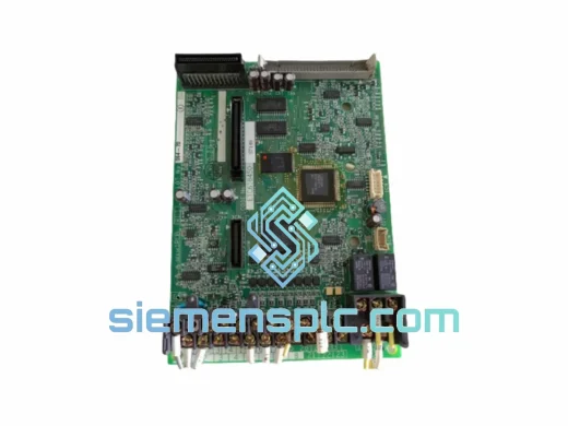
YASKAWA YPHT11017-1A Drive Control Board
Varispeed G7 F7 Series
Origin JP
PLC & Drive Control Board
Yaskawa
RFQ Ready
YASKAWA YPCT31240-1C Drive Control Board – Varispeed Series
F7 Series
Origin JP
Drive Control Board
Yaskawa
RFQ Ready
YASKAWA YPCT21092-1-4 Inverter Control Board
Industrial VFD
Origin JP
Inverter Control Board