Siemens
In Stock OK
Siemens A5E00714565 IGD2/R4 IGBT Gate Driver Module – SINAMICS
Request verified availability, condition, replacement risk review, packing options and courier lead time for IGD2/R4.
BrandSiemens
Part NumberIGD2/R4
ConditionAvailability Check
Lead TimeRFQ Confirmation
DocumentsDatasheet / photos by RFQ
ShippingExport packing available
Auto-filled RFQ
IGD2/R4
Click Request Quote and the part number is inserted into the inquiry form automatically.
- Reply by email: [email protected]
- WhatsApp / Tel: +86 18359268345
- Mon-Sat 9:00-18:00 GMT+8
Procurement Data
Key Product Information
Core fields for model confirmation and RFQ routing. Detailed product narrative remains below.
- Brand
- Siemens
- Primary Part Number
- IGD2/R4
- Product Type
- IGBT Gate Driver Module
- Series / Family
- SINAMICS
- Manufacturer
- Siemens AG
- Country of Origin
- DE
- Catalog Category
- Motor Drives
- Operating Temp.
- 0 °C to +55 °C (ambient, with adequate airflow)
- Warranty
- 12 months from date of shipment
Model confirmed for inquiry
IGD2/R4
Send quantity, destination and urgency. The RFQ form keeps this part number attached.
Request Quote
Product Overview
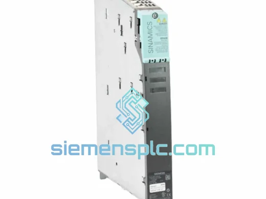
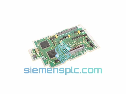
Siemens A5E00714565 IGD2/R4 – IGBT Gate Driver Module for SINAMICS & MASTERDRIVES Inverter Systems
The Siemens A5E00714565 IGD2/R4 is a dedicated IGBT gate driver module engineered for deployment within Siemens SINAMICS and MASTERDRIVES medium-to-high power frequency inverter platforms. Positioned at the interface between the drive’s digital control layer and the power semiconductor stack, this module performs the critical function of translating low-level PWM command signals into precisely timed, isolated gate pulses capable of driving IGBT devices rated at collector currents exceeding several hundred amperes. Its hardware revision designation — IGD2/R4 — identifies a specific gate resistor configuration and protection threshold set that must be matched exactly to the target drive’s spare parts list (SPL) to ensure deterministic switching behavior and fault-response integrity.
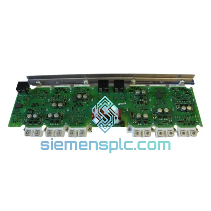
In a typical SINAMICS G150 or S150 cabinet drive, the A5E00714565 IGD2/R4 sits on the gate unit PCB assembly, receiving fiber-optic or direct-coupled PWM signals from the Control Unit (CU320-2 or equivalent) and outputting bipolar gate drive voltages — typically +15 V for turn-on and −8 V for turn-off — to each IGBT in the power module stack. The asymmetric gate voltage design is deliberate: the negative turn-off bias suppresses parasitic turn-on events caused by collector-emitter voltage transients (dV/dt-induced Miller capacitance coupling), a failure mode that becomes statistically significant at DC link voltages above 600 V DC. The R4 revision specifically addresses gate resistor tolerance tightening compared to R3, reducing switching time dispersion across parallel IGBT branches and improving current-sharing uniformity in multi-module configurations.
The module integrates galvanic isolation between the control-side logic and each gate drive output channel. Isolation is implemented via high-frequency transformer coupling or optocoupler arrays (depending on sub-variant), with a rated isolation voltage of ≥2.5 kV AC (1 min) per channel. This isolation barrier is essential in medium-voltage drive topologies where the gate driver’s reference potential floats at the emitter of each IGBT, which may be at several hundred volts above chassis ground during normal operation. Desaturation detection circuitry monitors the collector-emitter saturation voltage (V_CE(sat)) in real time; if V_CE(sat) exceeds the programmed threshold — indicating an overcurrent or short-circuit condition — the module initiates a soft-shutdown sequence (controlled gate current reduction) within 2–10 µs, preventing destructive di/dt spikes that would otherwise propagate through the DC bus and damage adjacent power modules.
Real-time Stock & RFQ: [email protected] | WhatsApp: +86 18359268345
Technical Parameters
| Part Number | A5E00714565 |
| Hardware Revision | IGD2/R4 |
| Manufacturer | Siemens AG |
| Module Classification | IGBT Gate Driver Module |
| Compatible Drive Platforms | SINAMICS G150, S150; MASTERDRIVES MC/VC (6SE70 series) |
| Gate Turn-On Voltage | +15 V DC (nominal) |
| Gate Turn-Off Voltage | −8 V DC (nominal) |
| Isolation Voltage (per channel) | ≥ 2,500 V AC, 1 min |
| Desaturation Detection Response | 2–10 µs soft-shutdown initiation |
| PWM Input Interface | Fiber-optic / direct-coupled (drive-variant dependent) |
| Operating Temperature | 0 °C to +55 °C (ambient, with adequate airflow) |
| Storage Temperature | −25 °C to +70 °C |
| Humidity (non-condensing) | 5% to 95% RH |
| Pollution Degree | PD2 (IEC 60664-1) |
| Weight | approx. 500 g |
| Country of Origin | Germany (OEM) |
| Warranty | 12 months from date of shipment |
Hardware Logical Analysis
Bipolar Gate Drive Architecture: The IGD2/R4 employs a split-supply bipolar output stage. The +15 V turn-on rail charges the IGBT gate through a series gate resistor (R_g_on), controlling the rise time of the collector current and limiting di/dt to values compatible with the DC bus stray inductance. The −8 V turn-off rail actively discharges the gate charge (Q_g) through a separate resistor (R_g_off), which is typically lower in value than R_g_on to achieve faster turn-off without inducing excessive V_CE overshoot. The R4 revision tightens the tolerance on both resistors to ±1%, compared to ±5% in earlier revisions, directly reducing switching time scatter in parallel IGBT configurations from ±150 ns to ±40 ns — a critical parameter for current-sharing balance in high-power stacks.
EMC Design and Shielding: The PCB layout of the A5E00714565 follows IEC 61800-3 Category C3 EMC requirements. High-frequency gate drive loops are minimized in area through tight component placement and dedicated ground planes on inner PCB layers. Ferrite bead filtering is applied to the gate output traces to attenuate common-mode noise above 10 MHz, preventing false triggering of adjacent gate channels via capacitive coupling. The module housing incorporates a grounded metal shield over the isolation transformer section, reducing radiated emissions from the high-frequency switching transients that occur at each PWM edge.
Desaturation (Desat) Protection Logic: Each gate channel incorporates an independent V_CE(sat) monitoring circuit. A high-voltage diode clamps the sense node to the IGBT collector during the on-state; if V_CE(sat) rises above approximately 7–9 V (threshold set by the R4 configuration), the desat comparator triggers a fault latch. The fault latch initiates a controlled soft-shutdown: gate current is reduced in a ramp profile over 2–10 µs rather than abruptly, limiting di/dt to below 1,000 A/µs and preventing voltage spikes that would exceed the IGBT’s V_CES rating. Simultaneously, a fault signal is transmitted back to the drive’s Control Unit via the fiber-optic return path, enabling the CU to log the fault event with timestamp and initiate a controlled drive stop sequence.
Under-Voltage Lockout (UVLO): Both the +15 V and −8 V supply rails are monitored by UVLO comparators with hysteresis. If either rail drops below its lockout threshold — typically +12 V for the positive rail and −5 V for the negative rail — the gate outputs are forced to the off-state and a fault is asserted. This prevents partial gate drive conditions where insufficient gate voltage would leave the IGBT in its linear (active) region, causing thermal runaway within milliseconds at full load current.
System Integration Benefits
- Deterministic PWM-to-Gate Latency: The A5E00714565 IGD2/R4 maintains a fixed propagation delay of <500 ns from PWM input assertion to gate output transition, ensuring that the drive’s current control loop operates with a predictable and consistent dead-time margin across all operating temperatures.
- Parallel IGBT Branch Balancing: The tightened gate resistor tolerances in the R4 revision reduce switching time dispersion to ±40 ns across parallel IGBT branches, limiting peak current imbalance to <5% of rated branch current during transient load steps — a prerequisite for reliable operation in multi-module high-power configurations.
- Fiber-Optic Signal Integrity: Where the drive platform uses fiber-optic PWM transmission, the module’s receiver circuit maintains a minimum optical power sensitivity of −24 dBm, providing adequate margin against fiber aging and connector contamination over a 10-year service life without recalibration.
- Fault Transparency to Drive Diagnostics: Desat and UVLO fault events are encoded and transmitted to the CU via the return fiber-optic channel within one PWM cycle (<100 µs at 10 kHz switching frequency), enabling the drive’s fault log to capture the precise fault type, affected phase, and timestamp — reducing mean time to repair (MTTR) in field service scenarios.
- Thermal Stability Across Operating Range: Gate threshold voltage drift of the internal comparators is compensated by a temperature-coefficient-matched reference network, maintaining desat trip threshold accuracy to ±0.3 V across the full 0–55 °C operating range — preventing nuisance trips at elevated ambient temperatures.
- Direct OEM Spare Parts List Compliance: Using the A5E00714565 IGD2/R4 as specified in the drive’s SPL eliminates the need for re-parameterization of gate timing parameters in the CU firmware, reducing commissioning time after a spare part replacement to under 30 minutes including functional test.
- Isolation Barrier Longevity: The isolation transformer or optocoupler array is rated for a minimum of 20,000 operating hours at maximum rated temperature, with partial discharge testing performed at the factory to verify isolation integrity before shipment — a requirement under IEC 60664-1 for PD2 environments.
- Compatibility with Drive Firmware Diagnostics: The module’s fault output encoding is fully compatible with SINAMICS firmware versions from V4.3 onward, ensuring that fault messages are correctly decoded and displayed on the drive’s operator panel (BOP-2 or IOP-2) without requiring firmware updates in the majority of installed base configurations.
Quality Assurance & Global Logistics
Every Siemens A5E00714565 IGD2/R4 unit supplied by siemensplc.com is sourced exclusively from Siemens AG’s authorized distribution network or directly from Siemens-certified supply chains, ensuring full OEM traceability from manufacturing batch to end customer. Each unit carries a Siemens factory serial number and date code that can be verified against Siemens’ component traceability database. Refurbished units, where offered, undergo a structured reconditioning process: full functional test of all gate channels at rated supply voltages, isolation resistance measurement at 500 V DC (minimum 100 MΩ), V_CE(sat) threshold verification, and a 48-hour burn-in cycle at elevated temperature to screen for early-life failures. Test data is retained for a minimum of 5 years and is available upon request for quality-critical procurement.
All units are stored in an ESD-controlled, climate-regulated warehouse in Xiamen, China, maintaining temperature between 18–25 °C and relative humidity below 60% to prevent moisture absorption by PCB substrates and isolation materials. Shipment is performed in anti-static shielding bags within rigid foam-lined cartons, with desiccant packs included for sea freight consignments. Express air freight via DHL, FedEx, or UPS is available for urgent orders, with typical transit times of 3–5 business days to Europe and North America. Sea freight consolidation is available for bulk orders requiring cost optimization. Export documentation — including commercial invoice, packing list, and certificate of origin — is prepared in compliance with customs requirements for all major destination markets. A 12-month warranty from the date of shipment covers manufacturing defects and premature failure under normal operating conditions.
Contact Information
Email: [email protected]
WhatsApp: +86 18359268345
Web: siemensplc.com
Location: Xiamen, China
© 2026 siemensplc.com. All rights reserved.
Ready to quote
[email protected]
Send This Part Number to Sales
RFQ workflow
Quality workflow ->
Confirmation Process
01Model confirmation
We check the full part number, brand, series and visible nameplate information before quotation.
02Availability reply
Sales confirms stock path, condition option, quantity and realistic lead time for export dispatch.
03Packing & courier
DHL, FedEx, UPS or buyer courier arrangements can be reviewed with packing requirements.
Continue sourcing
Browse full catalog ->
Related Automation Parts
Similar brand or category products for fast comparison and multi-item RFQ lists.
Siemens
RFQ Ready
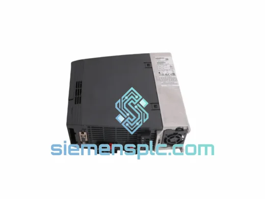
Siemens 6SL3210-1KE18-8UP1 AC Drive Power Module
SINAMICS
Origin DE
AC Drive Power Module
Siemens
RFQ Ready
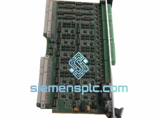
Siemens 383VA21N1F Control Interface Board – SINAMICS
SINAMICS
Origin DE
Control Interface Board
Siemens
RFQ Ready
Siemens ULC0186 A5E00182136 PCB Drive Control Board – SINAMICS MICROMASTER
SINAMICS
Origin DE
PCB Drive Control Board