Siemens
RFQ Ready
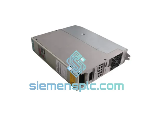
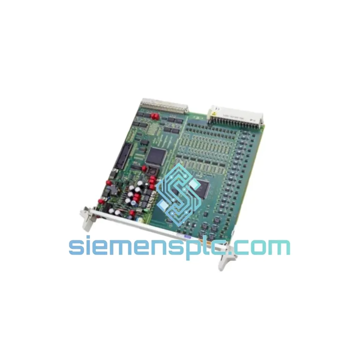
Siemens 6SE7031-7HG84-1JA1 Power Supply Module
SIMOVERT
Origin DE
PLC Power Supply Module
Request verified availability, condition, replacement risk review, packing options and courier lead time for 6DP1232-7AA.
Click Request Quote and the part number is inserted into the inquiry form automatically.
Core fields for model confirmation and RFQ routing. Detailed product narrative remains below.
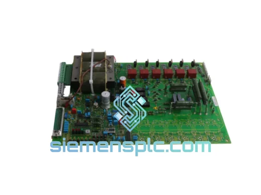
The Siemens 6DP1232-7AA is a slot-mounted encoder interface module developed for the 6DP-series rack platform used in SIMOVERT MASTERDRIVES Motion Control (MC) and Vector Control (VC) configurations. Its function sits at the boundary between the physical encoder transducer and the drive’s digital control core — a position that makes it one of the most consequential hardware nodes in any precision motion or process drive system.
Incremental encoders generate raw quadrature pulse trains that carry velocity and position information, but those signals arrive at the drive cabinet having traveled through cable runs that may span 30 to 100 meters in large machine tool or process line installations. Over that distance, the signal is subject to capacitive loading, differential impedance mismatch, common-mode voltage shifts from ground potential differences between the motor end and the cabinet, and radiated EMI from adjacent power cables. The 6DP1232-7AA’s hardware architecture is designed to absorb all of these degradation mechanisms before the signal reaches the drive’s position counter and speed calculation registers.
The module accepts both TTL-level differential signals (5 V, RS-422 compatible) and HTL-level signals (10–30 V DC, single-ended or differential) on the A, B, and Z channels. This dual-voltage input architecture means the module can interface directly with the broad range of incremental encoders used across Siemens and third-party servo motor platforms without requiring external signal converters or additional terminal block wiring. The input stage presents a defined 120 Ω differential termination impedance to the encoder cable, which suppresses standing wave reflections on long cable runs — a source of pulse edge jitter that degrades velocity loop bandwidth in high-dynamic applications.
Following the input termination stage, the signal passes through a galvanic isolation barrier implemented with high-speed optocouplers. The isolation rating is sufficient to withstand the common-mode transient voltages that appear on encoder cable shields in multi-drive systems sharing a common DC bus — environments where ground potential differences of several volts between cabinet and motor frame are routine. This barrier prevents those ground loop currents from coupling into the drive’s control ground reference, which would otherwise appear as low-frequency noise on the velocity feedback signal and manifest as speed ripple at the motor shaft.
The Z-channel (index pulse) receives dedicated latch processing. Rather than passing the index pulse through the same asynchronous path as the A/B quadrature channels, the module captures the Z event synchronously with the quadrature count register. This prevents the index pulse from being sampled across a count boundary — a failure mode that produces inconsistent home position offsets across power cycles and is particularly damaging in CNC homing sequences and servo press bottom-dead-center detection.
Configuration of the module — encoder pulse-per-revolution count, signal type selection (TTL/HTL), and filter time constants — is stored in the SIMOVERT drive’s parameter set and downloaded to the module via the 6DP backplane bus at power-up. This means a module replacement in the field does not require re-entry of encoder interface parameters. The maintenance technician installs the replacement module, powers up the drive, and the backplane initialization sequence restores the full configuration. This architecture directly reduces mean time to repair (MTTR) in production environments where re-commissioning by a drive specialist is not immediately available.
Real-time Stock & RFQ: [email protected] | WhatsApp: +86 18359268345
| Parameter | Specification |
|---|---|
| Part Number | 6DP1232-7AA |
| Manufacturer | Siemens AG |
| Product Family | 6DP Series / SIMOVERT MASTERDRIVES |
| Module Function | Incremental Encoder Signal Conditioning & Backplane Interface |
| TTL Input Specification | 5 V differential, RS-422 compatible, A/B/Z channels |
| HTL Input Specification | 10–30 V DC, single-ended or differential, A/B/Z channels |
| Input Termination Impedance | 120 Ω differential (TTL mode) |
| Maximum Input Pulse Frequency | Up to 300 kHz (application and PPR dependent) |
| Galvanic Isolation | Opto-isolation, encoder terminals to backplane logic |
| Z-Channel Processing | Synchronous latch capture, count-boundary safe |
| Backplane Interface | 6DP parallel data bus, slot-addressed |
| Configuration Method | Drive parameter set, downloaded via backplane at power-up |
| Operating Temperature | 0 °C to +55 °C |
| Storage Temperature | –25 °C to +70 °C |
| Relative Humidity | 5–95 %, non-condensing |
| Mounting | 6DP-series rack slot |
| Country of Origin | Germany |
| Approximate Weight | 300 g |
| Warranty | 12 months from confirmed shipment date |
The internal signal chain of the 6DP1232-7AA follows a four-stage processing architecture, each stage addressing a specific signal integrity or system integration requirement.
Stage 1 — Input Impedance Matching and Level Translation. The encoder input terminals connect to a front-end network that simultaneously provides cable termination and voltage scaling. For TTL inputs, the 120 Ω differential termination is placed at the module’s input — the correct location for termination in RS-422 topologies — rather than at the encoder end, which is the common wiring error that causes reflection-induced pulse edge distortion on cables longer than approximately 10 meters at 300 kHz. For HTL inputs, a precision resistive divider scales the 10–30 V signal to a level compatible with the optocoupler input stage without exceeding the coupler’s forward current rating across the full HTL voltage range.
Stage 2 — Opto-Isolation Barrier. High-speed optocouplers with propagation delays below 1 µs are used to maintain pulse fidelity at the module’s maximum rated input frequency. The isolation barrier’s common-mode rejection characteristic is the primary EMC defense in the signal path. In drive cabinet environments where multiple axes share a common DC bus, the ground potential at the motor frame can differ from the cabinet control ground by 2–10 V at power frequencies, with transient spikes reaching significantly higher during switching events. The isolation barrier prevents these potentials from appearing as differential noise on the A/B channels, which would otherwise be indistinguishable from encoder pulses at the position counter input.
Stage 3 — Z-Channel Synchronous Latch. The index pulse latch is clocked by the same reference used to sample the A/B quadrature channels. This ensures that when the Z pulse arrives, the associated quadrature count value is captured atomically — the count register and the index flag are updated in the same clock cycle. Systems that process the Z channel asynchronously are vulnerable to a race condition where the index event is recorded one count position away from the true index location, producing a ±1 count home position uncertainty that accumulates into measurable position error in multi-cycle homing routines.
Stage 4 — Backplane Data Formatting and EMC Filtering. The conditioned digital signals are formatted into the data word structure expected by the 6DP backplane bus and transmitted to the drive’s position counter registers. Ferrite bead filtering at the backplane connector suppresses high-frequency noise injected from the bus during IGBT switching events in the drive’s power stage — a coupling path that is often overlooked in drive system EMC analysis but can introduce bit errors in backplane communication at high switching frequencies.
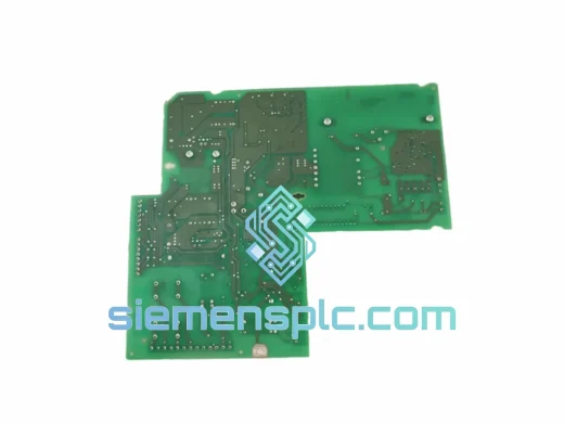
The PCB layout follows Siemens’ internal design rules for drive-mounted electronics: separate copper pours for analog input ground and digital backplane ground, with the isolation barrier physically separating the two domains. High-frequency signal traces are routed with controlled impedance and guarded with ground traces to minimize crosstalk between the A, B, and Z channels at the PCB level.
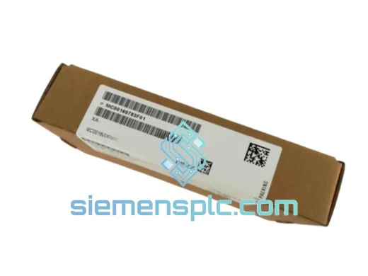
Every 6DP1232-7AA unit shipped from siemensplc.com is sourced as genuine Siemens OEM hardware. Incoming units are inspected against OEM reference documentation: part number markings, PCB revision labels, connector condition, and physical integrity are verified before acceptance into fulfillment stock. Units showing evidence of re-marking, non-OEM components, or physical damage are rejected at intake. Anti-static packaging with moisture barrier and desiccant is applied prior to dispatch, with a QC reference label traceable to the inspection record.
All shipments originate from our warehouse in Xiamen, China, a port city with direct cargo connections to major logistics hubs across Asia, Europe, and the Americas. Standard international express services (DHL Express, FedEx International Priority, UPS Worldwide Express) deliver to most destinations in Asia within 2–4 business days, Europe within 3–5 business days, and North America within 4–7 business days. Orders confirmed before 14:00 CST are eligible for same-day dispatch. Every shipment includes a commercial invoice, packing list, and certificate of origin to support import customs clearance. Batch traceability documentation and supplier certificates are available on request for regulated industry procurement requirements.
All units carry a 12-month warranty from the confirmed shipment date. Warranty claims are handled directly by our technical team — no third-party RMA routing. Confirmed faulty units are replaced or credited within 5 business days of fault verification. Multi-currency payment is supported: USD, EUR, HKD, CNY, and other major currencies accepted via wire transfer or trade finance arrangements for qualified buyers.
Email: [email protected]
WhatsApp: +86 18359268345
Web: siemensplc.com
Location: Xiamen, China
© 2026 siemensplc.com. All rights reserved. Product names and trademarks are the property of their respective owners. siemensplc.com is an independent supplier and is not affiliated with or endorsed by Siemens AG.
We check the full part number, brand, series and visible nameplate information before quotation.
Sales confirms stock path, condition option, quantity and realistic lead time for export dispatch.
DHL, FedEx, UPS or buyer courier arrangements can be reviewed with packing requirements.
Similar brand or category products for fast comparison and multi-item RFQ lists.