
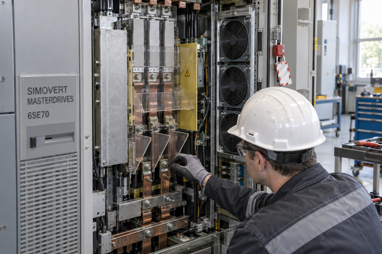
A drive fault that returns immediately after reset is a warning to slow down, not a reason to keep cycling power. On an older SIMOVERT MASTERDRIVES 6SE70 installation, the observed trip can reflect an incoming supply disturbance, DC-link condition, cooling problem, motor or cable fault, control electronics, parameter mismatch or a genuine power-stage failure. These boundaries carry high energy and present serious electrical hazards. Before anyone opens the cabinet or orders a module, establish the exact drive execution, preserve diagnostics and follow the site’s electrical safety and manufacturer procedures.
Capture the drive identity and the operating context
Record the complete drive type designation, order number, option boards, control unit, power section, firmware or parameter-set reference, cabinet location and motor nameplate data. Photograph labels and connections only if site rules permit. Note the fault code and text, operating mode, speed, load, DC-link indication, ambient conditions and the time of the trip. Preserve the parameter backup and fault history before resetting. Ask whether the event followed a power quality disturbance, motor work, cable replacement, cooling-system maintenance or parameter download.
Identify what the application was doing when the trip occurred: acceleration, steady-state operation, deceleration, braking or restart. A fault only during one operating region may point toward a different boundary than an immediate power-up trip. Correlate the event with upstream breaker records, process history and motor protection indications. If system clocks differ, note the time offset before constructing a chronology.
Distinguish supply, DC link, load and drive faults
Review the manufacturer’s fault description and the approved plant procedure before interpreting a code. A trip name is a diagnostic clue, not a parts order. Compare the event with incoming phase and supply records, DC-link behavior, motor current, speed command and any external protection operation. Look for repeated undervoltage, overvoltage, overcurrent, ground-fault or temperature patterns, but do not assume the fault text proves which component is defective.
Inspect the motor and cable history. A damaged motor winding, insulation fault, incorrect cable termination, contamination or mechanical overload can stress a healthy power stage. Likewise, a blocked air path, failed fan, high cabinet temperature or dust accumulation can trigger thermal symptoms without an electronic module defect. Visual checks must be made only after the equipment is placed in the safe state required by the site procedure. Never treat the absence of a display as evidence that stored energy is gone.
Respect stored energy and work boundaries
MASTERDRIVES power sections contain hazardous voltages and stored DC-link energy. Isolate all relevant sources, apply lockout/tagout, wait the manufacturer-specified discharge interval and verify absence of voltage with the approved tester and method before contact. Observe arc-flash boundaries, PPE, approach restrictions and the site electrical safe-work program. Only qualified personnel should perform internal inspection or measurement. Do not short the DC bus, bypass interlocks or probe energized power terminals as an informal test.
Once a safe work boundary is established, inspect accessible cooling paths, fan status, contamination, connector seating and visible heat damage. Record what is found before cleaning or moving parts. Compare the cabinet and module arrangement with approved drawings. Evidence of a damaged component should be photographed and retained for engineering review; carbonization, arcing or repeated fuse operation requires escalation rather than immediate re-energization.
Use the exact power-module identity
SiemensPLC lists a Siemens A5E00381705 AC drive power module for the 6SE70 series. Use that listing as an identity reference only. Confirm the complete order number and suffix, power rating, voltage class, hardware execution, cooling arrangement and compatibility with the specific control unit and cabinet. Similar-looking drive modules can differ in ratings, terminals, firmware dependencies or system generation. The catalog’s separate 6SE7090-0XX84-0FF5 SIMOVERT control-board reference is a different functional assembly, not an alternate power module. Verify each characteristic against the installed nameplate, manufacturer documentation and approved bill of material.
Retain the failed unit’s labels and record the as-found connections, parameter set, fault history and any visible damage. For an RFQ, state the exact code, revision, drive and motor details, required condition, fault chronology, test evidence requested and outage deadline. A used or repaired component should be described accurately, with its inspection and test scope explicit. A catalog result does not establish stock, remaining life or suitability for a particular application.
Plan an outage and acceptance sequence before replacement
Agree the work boundary with operations, electrical maintenance and drive specialists. Confirm process consequences, backup drive or bypass arrangements, isolation points, lifting or handling needs, permitted replacement procedure and stop-work criteria. Preserve a verified parameter backup and a rollback plan. If the drive is part of a coordinated system, identify associated PLC, communications, motor protection and mechanical checks that must be repeated after replacement.
After approved installation, inspect terminals and connections, restore covers, verify grounding and confirm all tools and temporary leads are removed. Follow the manufacturer’s commissioning steps for parameter verification, motor data, control mode, cooling and diagnostics. Test at the approved operating stage and load, monitoring current, temperature, alarms and process response. Operations must accept the returned function; a successful power-up alone does not prove that the drive is reliable under duty. Record as-left parameters and test results with the maintenance history.
Reduce repeat failures through evidence-based planning
For installed legacy drives, the useful maintenance record is more than an inventory count. Track drive identification, option configuration, motor pairing, firmware or parameter backups, fault history, cooling inspections, last functional test and spare condition. Review whether a single stored module would support the actual installed population or whether different ratings and executions are present. Set preservation and inspection requirements with the responsible engineering team. A common, well-documented configuration is easier to support than several undocumented variants.
When a recurring failure occurs, compare events across units and operating conditions. A plant-wide supply event, ventilation change or process load shift can affect multiple drives. Escalate trends early and retain failed parts for analysis where possible. This helps maintenance decide whether the right intervention is a module replacement, environmental correction, motor repair, parameter review or a planned modernization assessment.
Questions maintenance teams ask
Does a 6SE70 overcurrent trip prove the power module is bad?
No. Review the trip timing, motor and cable condition, load, supply, configuration and drive diagnostics. The code narrows the investigation but does not identify a failed part by itself.
How long should we wait before opening the drive?
Follow the exact manufacturer instructions for the installed execution, including discharge time and verification of absence of voltage. Never rely on a generic wait or display indication alone.
Can a similar 6SE70 module be substituted?
Not without checking the complete order number, voltage and power ratings, terminals, cooling, control unit, options and approved system design.
What should a drive power-module inquiry include?
Provide full drive and module labels, motor data, fault evidence, parameter backup reference, condition requirement, test documentation requested and planned outage date.
For a 6SE70 sourcing review, send SiemensPLC the full drive and module labels, motor details, fault history, cabinet photographs and outage schedule. We can help verify catalog identity and sourcing evidence; final application approval remains with your drive engineer.
© 2026 SiemensPLC. All rights reserved. Official Website: https://siemensplc.com Inquiry: [email protected] | WhatsApp/Tel: +86 592 683 453