ABB
In Stock OK
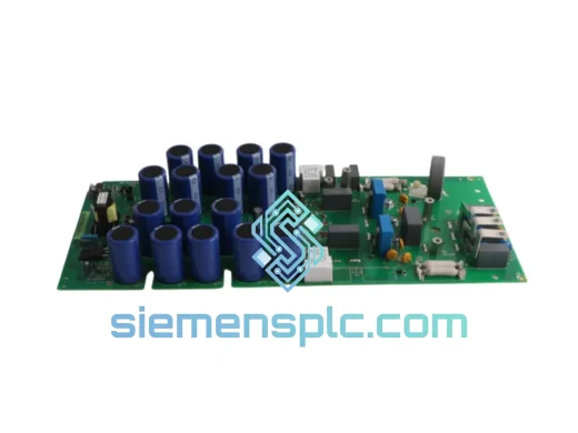
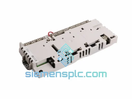
ABB NINT-53C Drive Interface Module – ACS800 Series
Request verified availability, condition, replacement risk review, packing options and courier lead time for NINT-53C.
BrandABB
Part NumberNINT-53C
ConditionAvailability Check
Lead TimeRFQ Confirmation
DocumentsDatasheet / photos by RFQ
ShippingExport packing available
Auto-filled RFQ
NINT-53C
Click Request Quote and the part number is inserted into the inquiry form automatically.
- Reply by email: [email protected]
- WhatsApp / Tel: +86 18359268345
- Mon-Sat 9:00-18:00 GMT+8
Procurement Data
Key Product Information
Core fields for model confirmation and RFQ routing. Detailed product narrative remains below.
- Brand
- ABB
- Primary Part Number
- NINT-53C
- Product Type
- Drive Interface Module
- Series / Family
- S800
- Manufacturer
- ABB
- Country of Origin
- SE
- Catalog Category
- Motor Drives
- Warranty
- 12 months from date of shipment
- Compliance
- CE, IEC 61800-3, RoHS
Model confirmed for inquiry
NINT-53C
Send quantity, destination and urgency. The RFQ form keeps this part number attached.
Request Quote
Product Overview
ABB NINT-53C: Main Circuit Interface Module in ACS800 Drive Control Architecture
The NINT-53C is ABB’s dedicated main circuit interface board for the ACS800 single-drive platform. Positioned between the IGBT power stage and the RMIO-02 control unit, this module performs three non-negotiable functions in the drive’s closed-loop architecture: it conditions and transmits DC bus voltage feedback, relays IGBT junction temperature signals via NTC thermistor chains, and provides the fiber-optic gate-pulse pathway that isolates the high-voltage switching domain from the low-voltage control domain. Without a correctly functioning NINT-53C, the ACS800 cannot execute its internal protection algorithms—overcurrent trip, overvoltage clamp, and thermal derating all depend on the signal integrity this board maintains.
Physically, the NINT-53C is a single-board assembly mounted inside the drive’s power module bay. Its connector layout is frame-specific: the 34-pin ribbon interface mates directly to the AINT-02C auxiliary interface or the RMIO control board depending on drive frame size (R2 through R7 for wall-mounted ACS800-01 units). The board carries a dedicated fiber-optic transceiver pair—one transmit channel for gate-pulse commands, one receive channel for fault acknowledgment—operating at 820 nm wavelength with a nominal link budget sufficient for the 0.5 m to 2 m intra-cabinet runs typical in ACS800 cabinet builds.
In terms of signal conditioning, the NINT-53C integrates a precision voltage divider network scaled to the drive’s DC bus range (nominally 513 V DC for 400 V AC input, up to 1,100 V DC for 690 V AC variants). The analog output of this divider feeds the RMIO’s ADC input, where the firmware maps raw counts to actual bus voltage with a resolution of approximately 1 V per LSB. This measurement underpins the overvoltage protection threshold (typically set at 130% of nominal DC bus) and the kinetic energy backup function used in process-critical applications such as paper machine section drives.
The thermal monitoring chain on the NINT-53C reads NTC sensors bonded to the IGBT module baseplate. The board’s signal path includes a linearization network that converts the highly nonlinear NTC resistance-temperature curve into a near-linear voltage ramp, reducing the computational burden on the RMIO firmware. Thermal derating begins at a configurable threshold (default 85°C junction estimate) and the drive trips at 100°C to prevent insulated gate bipolar transistor latch-up—a failure mode that would otherwise destroy the power module within milliseconds.
Real-time Stock & RFQ: [email protected] | WhatsApp: +86 18359268345
Technical Parameters
| Parameter | Value |
|---|---|
| Part Number | NINT-53C |
| Manufacturer | ABB |
| Compatible Drive Series | ACS800-01, ACS800-02, ACS800-04, ACS800-07 |
| Compatible Frame Sizes | R2 – R7 (single-drive units) |
| DC Bus Voltage Measurement Range | 0 – 1,200 V DC (scaled per frame) |
| Fiber-Optic Wavelength | 820 nm (HFBR-compatible) |
| Fiber-Optic Channels | 2 (1× TX gate pulse, 1× RX fault feedback) |
| Thermal Sensor Interface | NTC thermistor chain, linearized output |
| IGBT Thermal Trip Threshold | 100°C (junction estimate, firmware-configurable) |
| Operating Ambient Temperature | 0°C to +55°C |
| Storage Temperature | -40°C to +70°C |
| Relative Humidity (operating) | 5% – 95%, non-condensing |
| Board Dimensions (approx.) | Frame-dependent; R5 reference: 180 mm × 120 mm |
| Weight | Approx. 100 g |
| Mounting | Internal drive bay, plug-in ribbon + fiber connectors |
| Compliance | CE, IEC 61800-3, RoHS |
| Warranty | 12 months from date of shipment |
Hardware Logical Analysis
Galvanic Isolation via Fiber-Optic Gate Path. The NINT-53C’s most critical design feature is its fiber-optic isolation of the IGBT gate-drive signals. The control board (RMIO) generates PWM gate commands at logic level; the NINT-53C’s fiber transmitter converts these to optical pulses that cross the isolation barrier with no conductive path. This eliminates common-mode noise coupling from the switching node—where dV/dt events during IGBT commutation can exceed 5 kV/µs—into the control electronics. The result is a measured common-mode rejection that satisfies IEC 61800-3 Category C3 EMC requirements without additional external filtering on the control wiring.
DC Bus Voltage Divider Precision. The resistor network on the NINT-53C is laser-trimmed to a tolerance of ±0.5% across the operating temperature range. Thermal coefficient matching between the divider resistors ensures that the voltage measurement error remains below ±2 V across the 0°C to 55°C ambient range. This precision is necessary because the overvoltage protection algorithm uses the bus voltage measurement as its sole input—a 5% measurement error at 700 V DC would shift the trip threshold by 35 V, potentially allowing bus voltages that stress the IGBT’s collector-emitter breakdown rating.
NTC Linearization Network. Raw NTC resistance varies exponentially with temperature (Steinhart-Hart equation). The NINT-53C includes a passive linearization bridge that maps the 10 kΩ NTC at 25°C to a near-linear 0–5 V output across the 0°C to 150°C range. This reduces the RMIO firmware’s lookup table to 16 entries versus the 256 entries that would be required for direct NTC digitization, freeing processor cycles for real-time torque and flux calculations in the direct torque control (DTC) algorithm.
EMC Shielding and PCB Layout. The NINT-53C PCB uses a four-layer stackup with dedicated ground planes on layers 2 and 3. High-frequency signal traces (fiber-optic driver circuits, ADC input lines) are routed on the inner layers, shielded by the ground planes from the switching-frequency interference present in the power module bay. Decoupling capacitors (100 nF X7R ceramic, 10 µF electrolytic) are placed within 2 mm of each IC power pin, maintaining supply impedance below 1 Ω up to 10 MHz.
Fault Feedback Loop. The receive fiber channel carries a coded fault signal from the gate-drive board back to the RMIO. This signal encodes short-circuit detection (desaturation sensing on the IGBT) with a propagation delay of less than 2 µs from fault event to RMIO interrupt. The RMIO then executes a controlled shutdown sequence—ramping down gate pulses in a defined order to prevent shoot-through—within one PWM period (typically 200 µs at 5 kHz switching frequency).
System Integration Benefits
- Deterministic Protection Response: The fiber-optic fault feedback path delivers IGBT desaturation events to the RMIO within 2 µs, enabling controlled shutdown before thermal runaway propagates to adjacent power modules in multi-drive cabinet installations.
- Accurate DC Bus Monitoring: Laser-trimmed voltage divider (±0.5% tolerance) provides the RMIO with bus voltage data accurate to ±2 V, supporting precise overvoltage trip calibration and kinetic energy backup activation thresholds.
- Thermal Derating Transparency: Linearized NTC output allows the ACS800 firmware to display real-time IGBT temperature estimates on the drive panel (parameter 01.18), giving maintenance engineers early warning of cooling degradation before a thermal trip occurs.
- EMC Compliance Without External Filters: Fiber-optic isolation eliminates conducted interference on control wiring, allowing the ACS800 to meet IEC 61800-3 C3 limits in industrial environments without additional ferrite cores or shielded cable on the RMIO I/O terminals.
- Plug-Compatible Replacement: The NINT-53C connector pinout and fiber port positions are identical across hardware revisions /A through /C, allowing direct board swap without mechanical modification to the drive’s internal wiring harness.
- Reduced Firmware Overhead: The NTC linearization network offloads temperature curve computation from the RMIO processor, preserving CPU bandwidth for the 40 µs DTC torque calculation cycle that is the ACS800’s core performance differentiator.
- Diagnostic Parameter Support: The board’s signal outputs map directly to ACS800 diagnostic parameters (01.18 IGBT temperature, 01.05 DC bus voltage), enabling remote monitoring via fieldbus (PROFIBUS, Modbus, DeviceNet) without additional hardware.
- Long-Term Spare Parts Availability: The NINT-53C has remained form-fit-function stable across the ACS800 production run (1996–present), meaning a board sourced today is a valid replacement for drives installed over two decades ago without firmware or parameter changes.
Quality Assurance & Global Logistics
Every NINT-53C unit dispatched from our Xiamen, China facility is sourced exclusively from ABB’s authorized distribution network or verified industrial surplus channels with full traceability documentation. Each board undergoes a structured incoming inspection protocol: visual examination under 10× magnification for solder joint integrity, component seating, and PCB delamination; continuity verification on the fiber-optic transceiver ports using an 820 nm optical power meter; and a functional power-on test where the board is energized at nominal supply voltage and output signals are verified against ABB’s published reference values.
Units are packed in anti-static shielding bags with desiccant and humidity indicator cards, then placed in rigid foam-lined cartons rated for 1.5 m drop per ISTA 2A. Export documentation—commercial invoice, packing list, certificate of conformity, and HS code declaration (8537.10)—is prepared same day for orders confirmed before 14:00 CST. Shipping options include DHL Express (2–4 business days to Europe and North America), FedEx International Priority (3–5 days), and UPS Worldwide Expedited. For urgent plant-down situations, same-day dispatch is available for orders confirmed before 12:00 CST. All shipments are fully insured and tracked from our warehouse to the consignee’s door. A 12-month warranty covers manufacturing defects; warranty claims are processed within 5 business days of receipt of the returned unit.
Contact Information
Email: [email protected]
WhatsApp: +86 18359268345
Web: siemensplc.com
Location: Xiamen, China
© 2026 siemensplc.com. All rights reserved.
Ready to quote
[email protected]
Send This Part Number to Sales
RFQ workflow
Quality workflow ->
Confirmation Process
01Model confirmation
We check the full part number, brand, series and visible nameplate information before quotation.
02Availability reply
Sales confirms stock path, condition option, quantity and realistic lead time for export dispatch.
03Packing & courier
DHL, FedEx, UPS or buyer courier arrangements can be reviewed with packing requirements.
Continue sourcing
Browse full catalog ->
Related Automation Parts
Similar brand or category products for fast comparison and multi-item RFQ lists.
ABB
RFQ Ready
ABB SDCS-COM-5 3BSE006567R1 Fieldbus Communication Module
S800
Origin SE
Fieldbus Communication Module
ABB
RFQ Ready
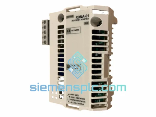
ABB RDNA-01 DeviceNet Adapter Module – ACS800 ACS600
S800
Origin SE
Fieldbus Communication Module
ABB
RFQ Ready
ABB RDCU-12C 3AUA0000036521 Drive Control Unit
S800
Origin SE
PLC & Drive Control Module